Assignment for this week:
Group assignment: Characterize your lasercutter’s focus, power, speed, rate, kerf, and joint clearance
Individual assignment: Cut something on the vinylcutter. Design, lasercut, and document a parametric construction kit, accounting for the lasercutter kerf, which can be assembled in multiple ways, and for extra credit include elements that aren’t flat
Introduction
This week I did vinyl cutting and laser cutting as well as developed skills in 2D and 3D design. I started using Inkscape and CorelDraw and FreeCAD this week. As this was my first experience in FreeCAD, first of all I watched some tutorials to get used to the tools and options. I did fully parametric design this week, which was exciting.
And the last but not least, this was my first experience with the vinyl cutter and laser cutter. It is a big responsibility to run both machines, so it’s important to read the user manuals and acknowledge the safety rules, before starting the cutting process.
- User manual Roland GS-24 Vinyl cutting Machine
- User manual for Epilog Laser MINI 18/24 & HELIX Laser cutter
- Vinyl cuttingBefore using the vinyl cutter I read the Manual of Roland GS-24 Machine That’s important for doing a proper cutting without destroying the machine and of course, to be familiar with safety policies. As the machine was well maintained before me, I didn’t have to change the blade, clean etc.
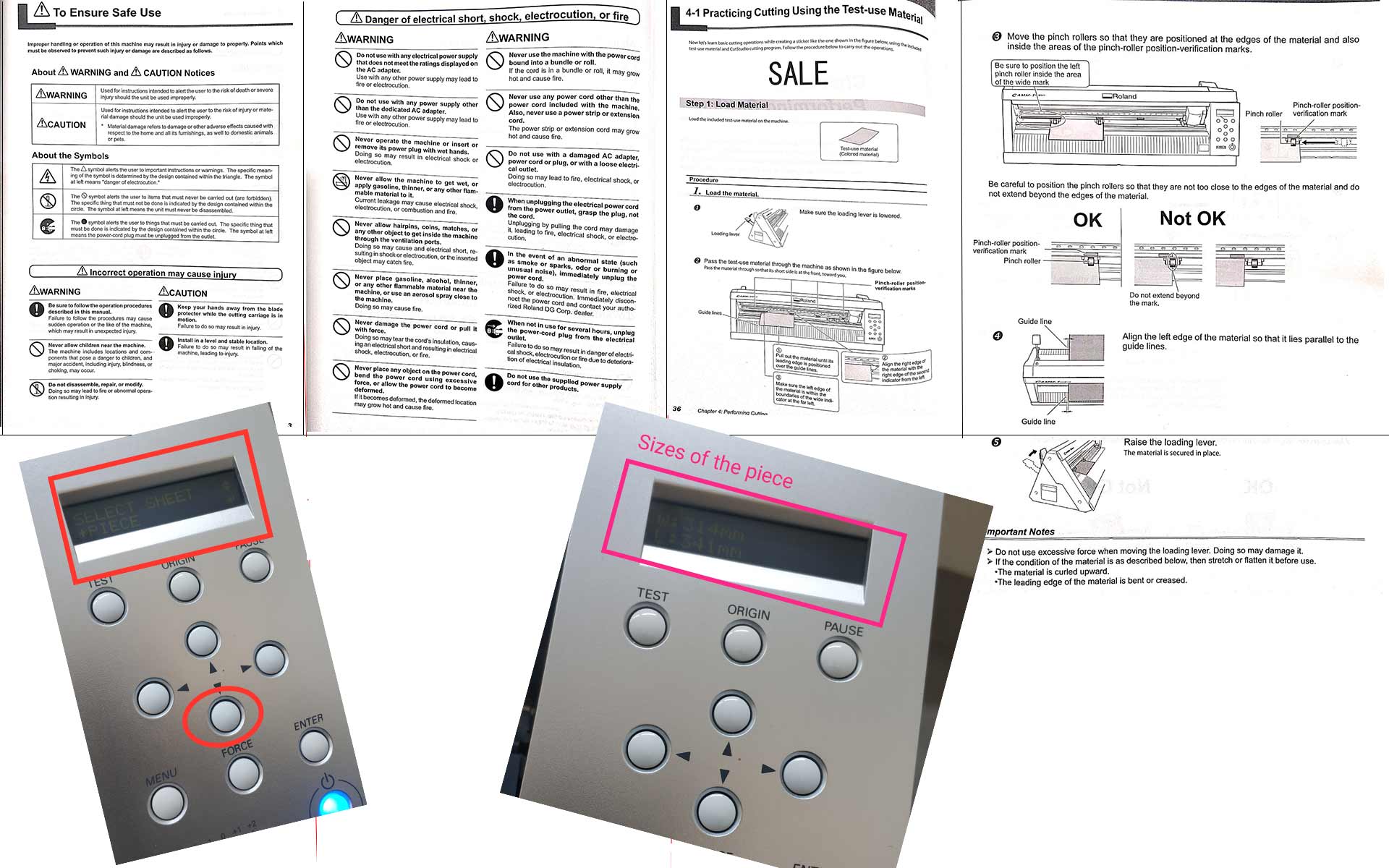
After choosing the material I want to cut on, I followed those steps for tsting the cutting force.
- Lower the loading lever
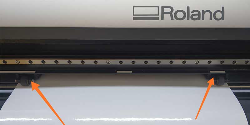
- Place the material in proper position under pinch rollers. We should remember that pinch rollers should be on white lines all the time. Edge of the material should be placed on one of the guide lines.
- Raise the loading lever
- Turn on the machine and press ↓ button. Then select PIECE then press ENTER. Then you will se the sizes of sheet avaliable for cutting
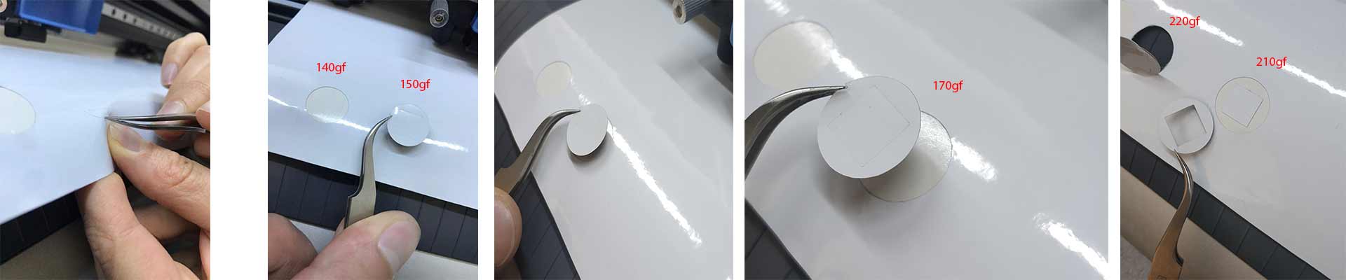
- Now it’s time to do a test to decide the cutting force. For that hold the TEST button for a second. It will cut a rectangle inside a square. If you can easily remove the “frame” of the rectangle, then you have the proper force. Otherwise you should adjust it. For that press the FORCE button and using arrows increase or decrease the force. In my case I put 140gf for the first trial, it was too low. Then I gradually increased till 220gf, which was too much and cut the base as well. So the optimum one was 210gf for my material.
- Start cuttng and have fun 🙂
After doing the test I was looking some vectors which I could use to cut nice shapes. On this website I found molecular models , downloaded .ai file and imported that to the Inkscape.
- As a first step, I selected all the objects, changed the Fill to No fill, Stroke line to solid black and the Stroke style to 0.01mm line . Those are the parameters, which are understandable for the vinyl cutter. Afterwards, go to File → Document Properties and add sizes received from machine. Then I moved objects close to each other, to not have waste of the material.
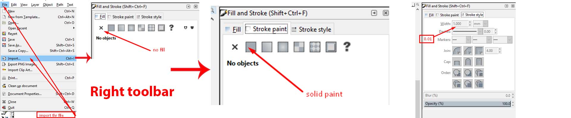
- Then go to File → Print, choose the model of your lasercutter. Then we have to go to Preferences and ask to take document sizes from machne or manually add them.
- Press Print and magic is happening. I used transfering tape for transfering the sticker to my phone case.
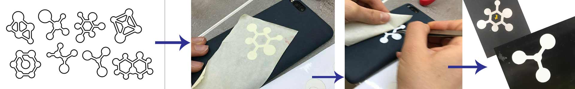
And the original file of my drawing is here
- Laser cutting Tolerance test for laser cutter
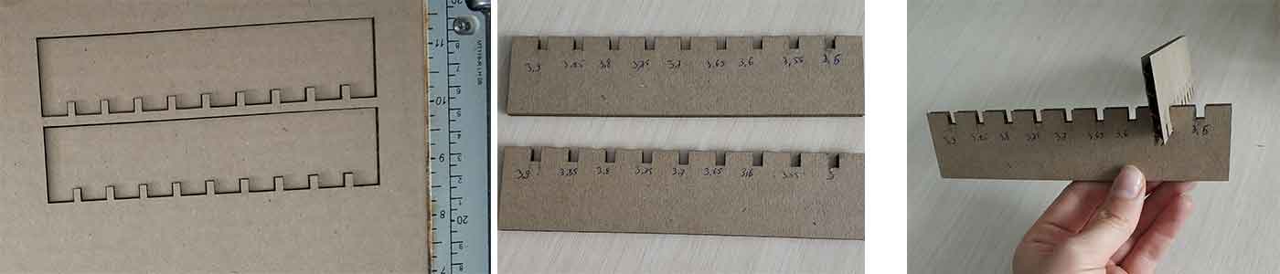
As I am going to cut a construction kit, which will have joints , it’s essential to design and cut kit parts properly, so that connections will be not too loose and not too tight. For that I did a tolerance test for the cardboard, which I was going to use. I measured thickness in different parts of the sheet using caliper and the minimum result was 3.8mm. I designed a comb-style part with different widths of holes started from 3.8mm to 3.5mm, and the step is 0.05mm. I did the whole design parametrically, which will allow me to use the same file for other thicknesses and if I decide to change the step value.
This time I used FreeCAD as a design tool, to be familiar with one more programm as well. Here is the step by step guide for designing tolerance test kit
- Open FreeCAD. Then press File → New file.
- On the toolbar choose Spreadsheet , to have a spreadsheet where you will add your parameters.
- Add parameters you want to use in your design. To activate them, right click on the value cell of your parameter, go to Alias tab and add a “nickname” for it. Also you have to go to Display unit tab and add parameter’s unit.
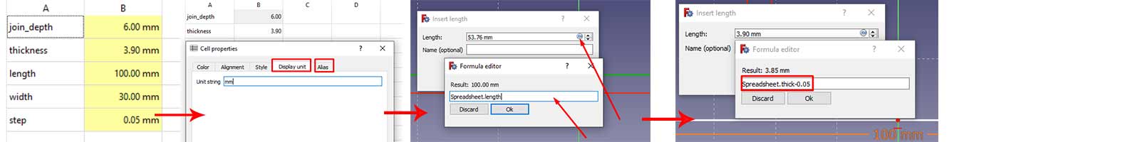
- After setting up parameters, go to your main file, in the toolbar select Part design, then create a sketch. Here you should select the plane you are going to sketch on and press OK.
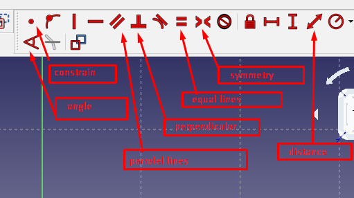
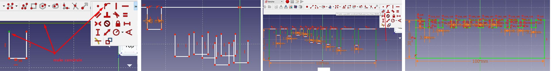
- There are different ways of designing comb. I decided to draw a main rectangle and on the top border draw small rectangles, attach them together and trim the unnecessary parts. This is not as easy as it seems at first sight. I have made constraints between edges of small rectangles and the top of the big one, made vertical edges parallel to each other, etc. Here you can see the list of the tools that I have used.
- I put the width of the first rectangle parameter of the thickness and for each next one subtracted number*step from the thickness. This way one can easily change the parameters for thickness and step without loosing the design.
- After finishing the sketch, I extracted the file as .svg file and moved to the computer, which is attached to the laser cutter.
- Here, using CorelDraw, I setted up the following parameters for my shapes ( we shall have 2 of the same parts)
Set fill to no fill
Set line color to solid black
Set line style to Hairline
Compared with Inkscape, here lines are remaining visible, even though they have the same thickness of 0.01mm. - Now my document is ready for printing (cutting).
Here are the original and .svg files:
Original file for tolernace test
File for laser cutterBefore starting to use the laser cutter, I have read the manual of the machine and with the instructors we got acquainted with the parts of laser cutter and principles of working with it. The most important things are to keep the machine tidy and maintained, and follow safety procedures.
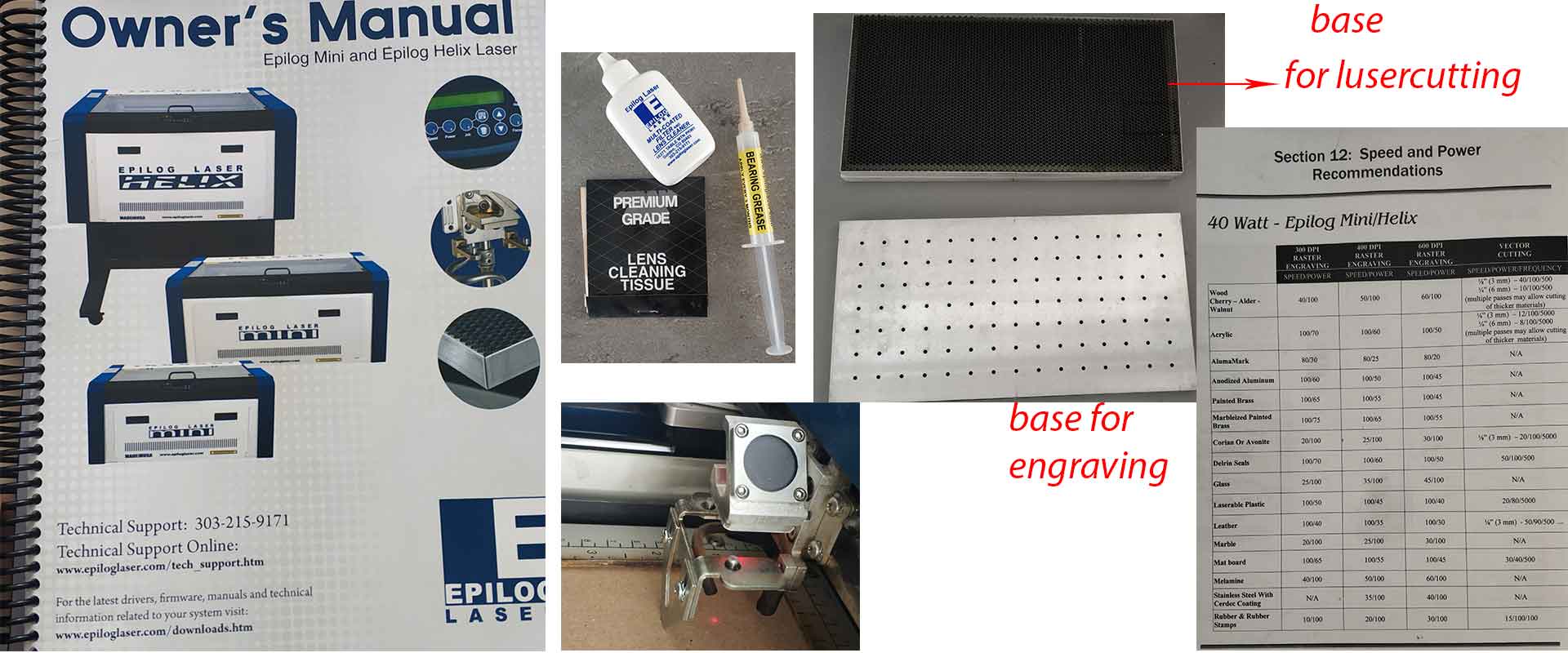
In the manual there are recommended speed, power and frequency for different materials.
Power
The power level directly controls the amount of energy in the laser. As power increases, the energy in the laser increases.
The amount of energy needed to penetrate will vary between materials and their thickness.
Since the laser cuts in a thin conical shape, more power will result in more perpendicular walls and a deeper cut, but will also mean more material removed.
High energy could also make more smoke and charred edges.
So, power is a necessity to reach a required cutting depth, but it is quite destructive to our materials. To make clear edges and less smoke, we should adjust the speed.
Speed
This setting changes the speed that the laser carriage will move.
The key to speed is that the longer the energy is exposed to a part, the more energy it will receive. Remember that high exposure to energy could result in smoke and charred edges.
Therefore, we use speed to control the length of time energy is on a point, thereby reducing the exposure to energy, yet still having the required amount to make a cut and avoid flames.
Increasing speed will also make the time of the project quicker. However, too much speed limits energy exposure and could make the cut too shallow.
As a conclusion we can say, that- More power = deeper cut = wide edges
- Less power = shallower cut = straighter edges
- Higher speed = faster cutting = shallower cut
- Lower speed = slower cutting = deeper cut
- Going too fast or too slow could result in undesirable edges.
To not waste a lot of cardboard, before cutting my drawing, I did cut one small rectangle with recommended parameters, to see if everything works well. The cut was perfect, so saved the same parameters for my actual job. Here are the results of my work, and as you can see the best parameter for thickness for this sheet is 3.55mm, even though the actual thickness is 3.8mm.
- Vinyl cuttingBefore using the vinyl cutter I read the Manual of Roland GS-24 Machine That’s important for doing a proper cutting without destroying the machine and of course, to be familiar with safety policies. As the machine was well maintained before me, I didn’t have to change the blade, clean etc.
Group assignment: Finding the kerf of the laser
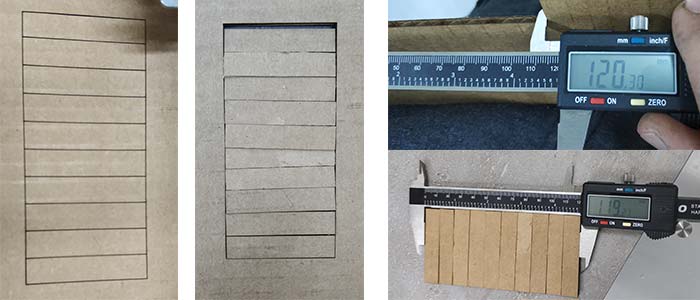
We used information from thsi source to find the kerf of the laser. We designed in CorelDraw and cut a rectangle with 10 rectangles in it. Thus, we have 11 line cuts.
After cutting, we merged together the small rectangles and measured the length of them together by caliper and got 119.27mm. Then we measured the size of the “frame” rectangle (120.30), subtracted from that oor first value and divided to 11.
(120.30-119.27)/11=0.09mm
So, the kerf of the laser is 0.09mm
- Designing and printing the construction kitI used FreeCAD to design a construction kit. I decided to make segments out of triangles, with a press-fit joint on one edge. And then, by creating a polar pattern around the central axis I will have polygon. Changing the number and the size of my triangles I will have different types and sizes of polygons.
I constructed the triangle with a joint in it using a line tool only. I put the top of the triangle in the center of the plane. Then made 2 parts of the triangle symmetrical to one axis.
Almost all of the lines and angles have parametric values, so I can change everything just by changing the parameters.
When the sketch of my triangle segment was ready, I used the pad tool to make it 3D. This gives thickness to the sketch, so I put the material thickness parameter.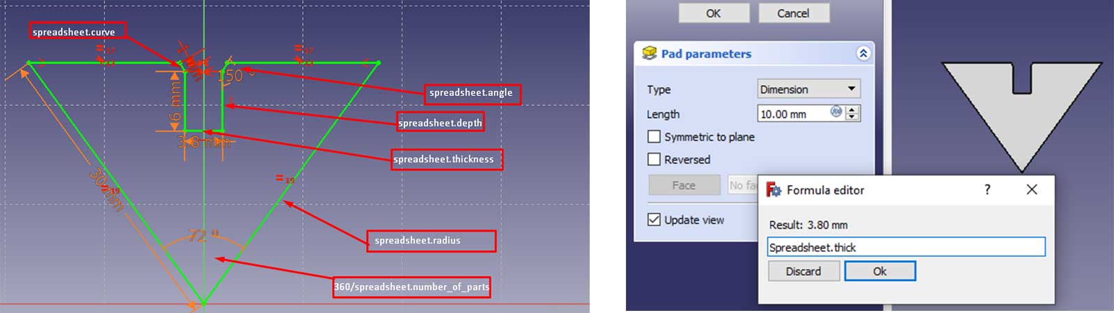
Then I applied Create a polar pattern tool on it. As a number of patterns, I put the number of my triangles.
To avoid having lines on the surface of my part, I went to polar pattern properties and put Refine parameter to true.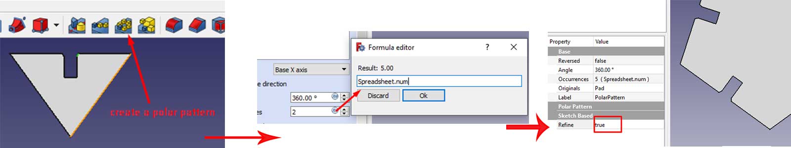
Now I have a pretty nice construction part.As I did for the tolerance test kit, this time as well I saved the file as .svg and did laser cutting.
I have imported the svg file of my construction kit to the CorelDraw program on a computer, which is connected to the laser cutter. Then changed parameters of the document as shown in the screenshot below.
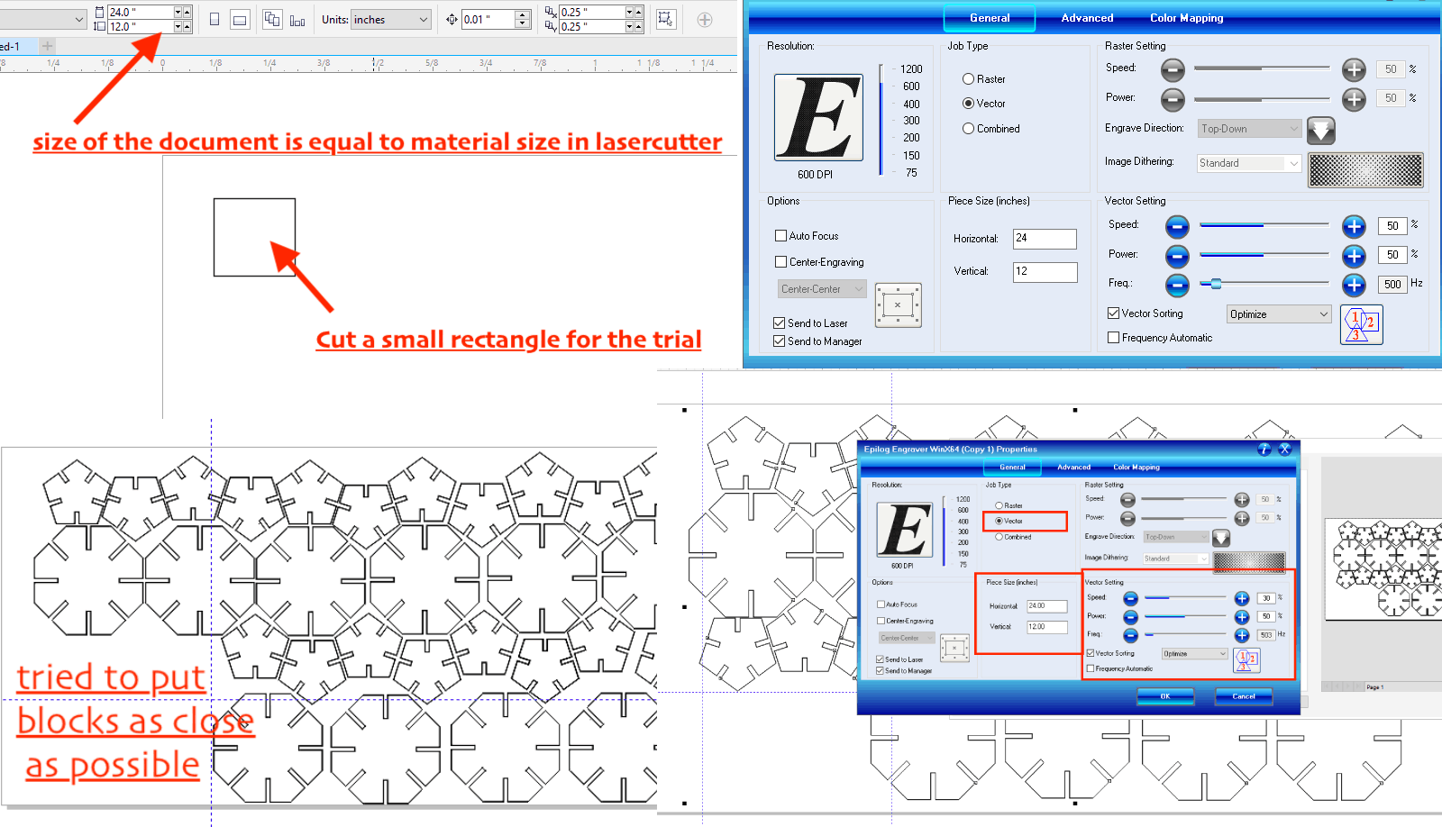
I made two types of parts: small pentagons and bigger octagons. After cutting with the same parameters as I had during the test, I took my created parts to my kids. They enjoyed playing with it and used their imagination to have different objects. We ended up having a pen box, a deer and there is more still to come.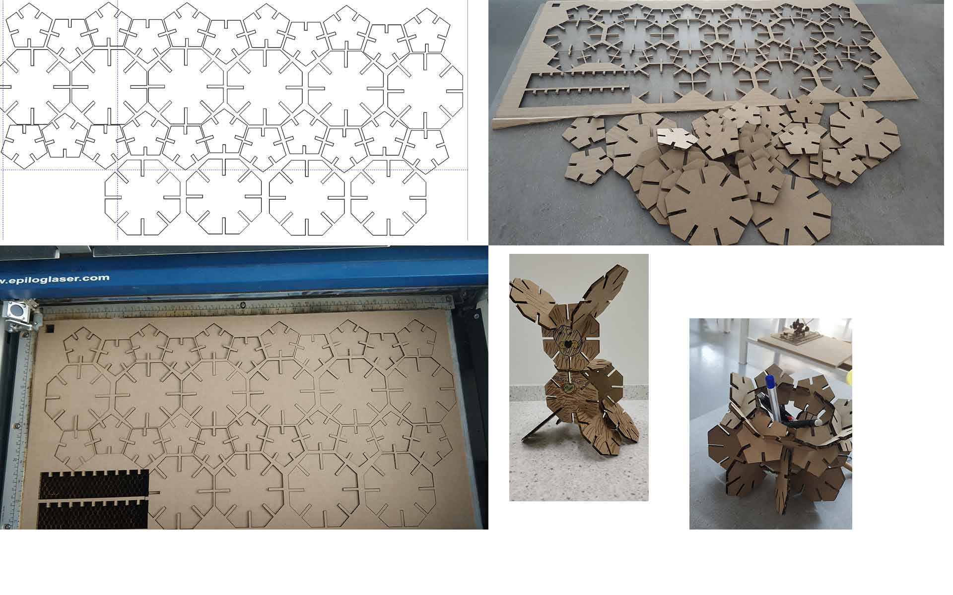
Inspired by what I’ve done so far and being already confident with FreeCAD, I designed the same kit with chamfer joints.
I had more experience using the laser cutter during my Final project. I have done laser cutting of the leather as well as engraving on the wood. You can check out the whole process in my Final project page.
- ConclusionThis weak I’ve learned basics of FreeCAD, which seemed difficult for me last week. Besides that, I’ve done some small steps in Inkscape and Coreldraw. For me the highlight of this week was the excitement from doing both vinylcutting and lasercutting. I leaned a lot about the machins, tips and tricks for using them as well as the safety rules for both.
- Files
File of molecules for vinyl cutter
Original file for tolernace test of laser cutter
SVG file for tolernace test of laser cutter
Cdr original file for finding the kerf
FCStd file for chamfer-joint kit
SVG file for chamfer-joint kit
FCStd file for press-fit joint kit
SVG file for press-fit joint part, big
SVG file for press-fit joint part, small
SVG file ready for laser cutting
Category:
AlumniDate:
February 3, 2022