

Maze of Birds 2.0: A Cooperative Game for Friends
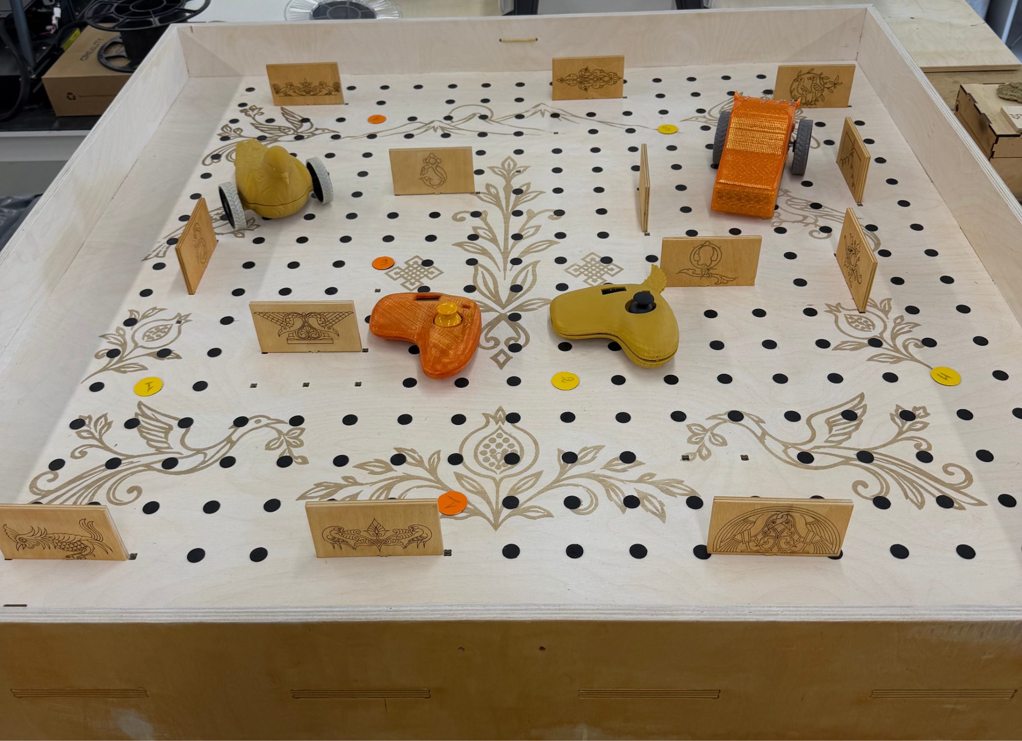
After Fab Academy I continued my final project. I engraved Armenian ornaments on the game board and walls, designed a new car and a new joystick, and turned Maze of Birds into a game two friends play together, with a Wio Terminal that creates every maze.
1. Project Overview
Maze of Birds was my final project for Fab Academy 2026: a small robot car, a joystick, NFC "coins" and a maze on a CNC-cut board. One player had to collect all the coins before the time was over.
When I graduated, I knew the game was not finished for me. 😄 I wanted it to look more Armenian, I wanted better hardware, and most of all I wanted friends to play it together.
This is what I changed after Fab Academy:
- Armenian ornaments engraved on the game board and the maze walls, and both varnished.
- An updated joystick: fixed OLED pins and a little bird wing on the case.
- A new bird-shaped car with one 3.7 V battery and a motor driver I built myself from MOSFETs.
- Two players, one team. Now it is a cooperative game: you win or lose together.
- A Wio Terminal that generates a new random maze every round and shows the score.
- New code for all five devices.
This page documents all of it. Each part has a short story first, then the technical details.
2. Concept: a game you play with friends
In the first version you played alone against the clock. Now there are two cars: Player 1 is orange and Player 2 is yellow. In Armenian I would call it a համագործակցային (cooperative) game, because the players don't compete with each other.
- Each player has 4 tags to find, so there are 8 tags on the board.
- Players have 3 minutes.
- The team wins only if both players find all their tags in time.
- If I finish first, my car stops, and now my job is to help my friend: "left… no, the other left!" 😄
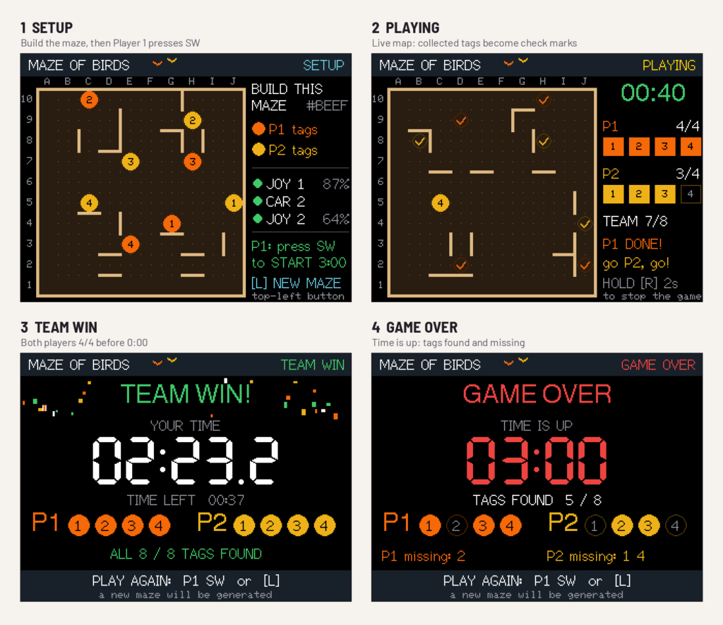
The Wio Terminal is the referee everyone can see. It shows the maze to build, the timer, the score of both players, and at the end a TEAM WIN or GAME OVER screen.
These are the four screens of the Wio Terminal:
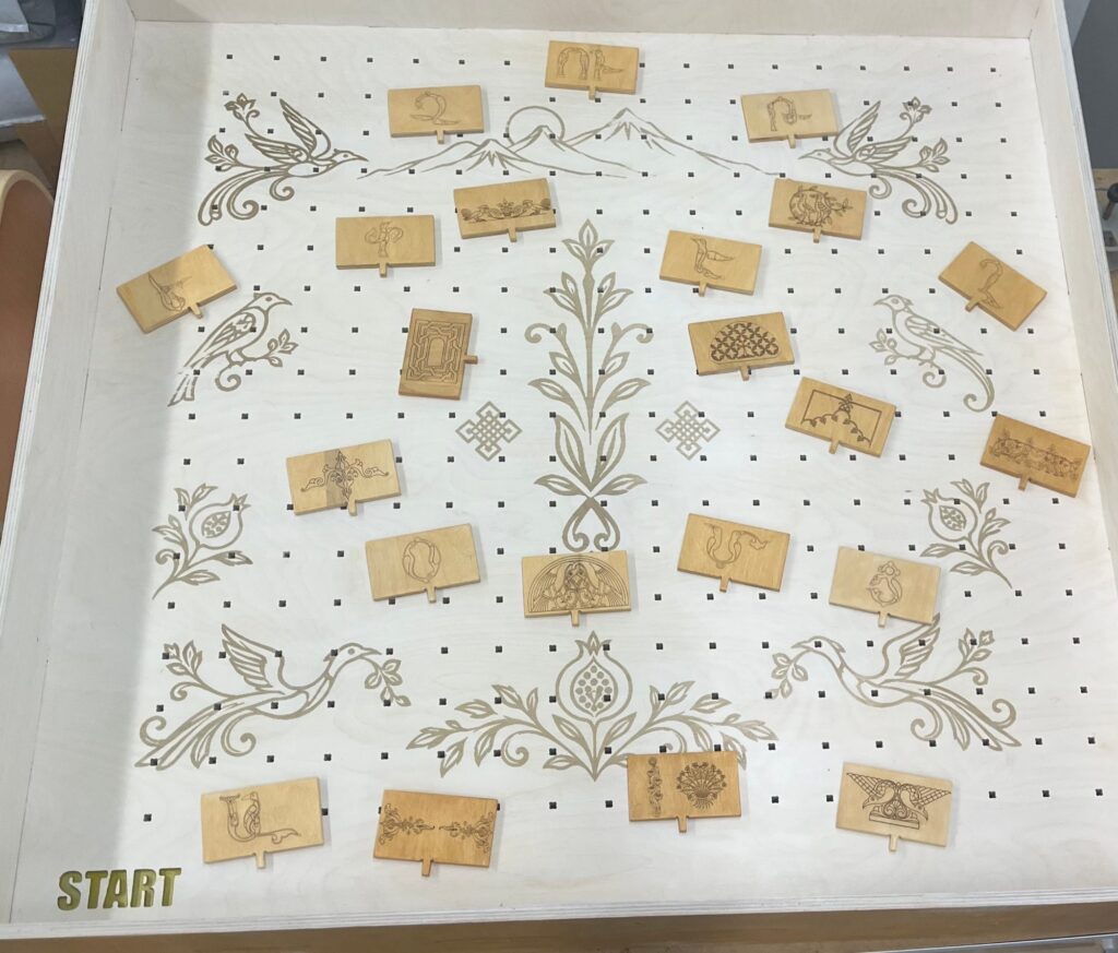
3. Armenian Ornaments on the Board and Walls
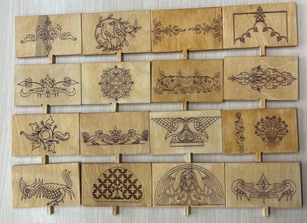
This was the first thing I did after graduation. During Fab Academy I had started engraving Armenian patterns and Bird Letters on the maze walls. Now I wanted the whole game to carry Armenian ornaments: the board and every wall.
Step 1: Choosing the ornaments
My source is the book Armenian Ornamental Art. The book exists only as a paid edition. My friends gave me .svg files made from it, with thousands of ornaments. I can't share a link to these files here, but if you are interested, write to me and I will send them to you.
Step 2: Preparing the files
After a long search I finally chose my ornaments. 😄 I used Inkscape only to work with the .svg files and to change the positions of some ornaments, so they fit on the walls.
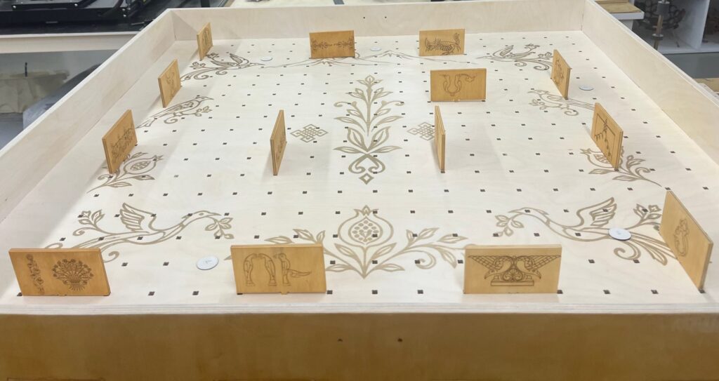
Step 3: Engraving the maze walls
I engraved the ornaments on the maze walls with these settings:
| Machine | Material | Settings |
|---|---|---|
| Laser cutter | Plywood maze walls | Speed 50, power 17–18 % |
Step 4: Engraving the game board
For the game board I collected several ornaments from the same files and arranged them the way I wanted. Then I engraved them on the board.
| Machine | Material | Settings |
|---|---|---|
| ✏️ [laser model] | Plywood game board, 1000 × 1000 mm | ✏️ [speed, power] |
Step 5: Varnishing
At the end I varnished the game board and all the maze walls with a varnish made for wood. It makes them look beautiful and helps the plywood last longer.
Here is the final result:
Safety note: Never leave the laser cutter running alone, and keep the air extraction on. Engraving makes a lot of smoke.
4. The New Joystick
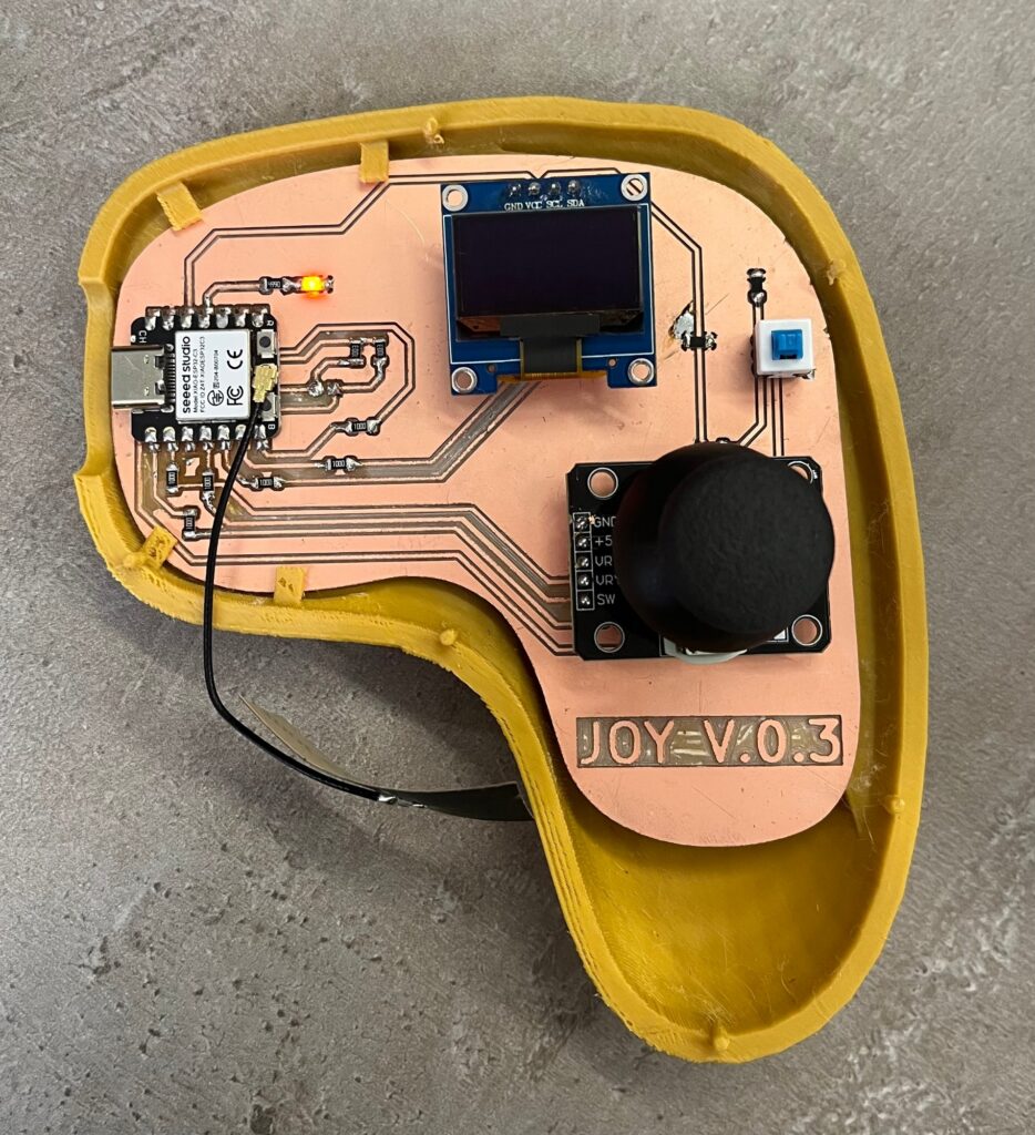
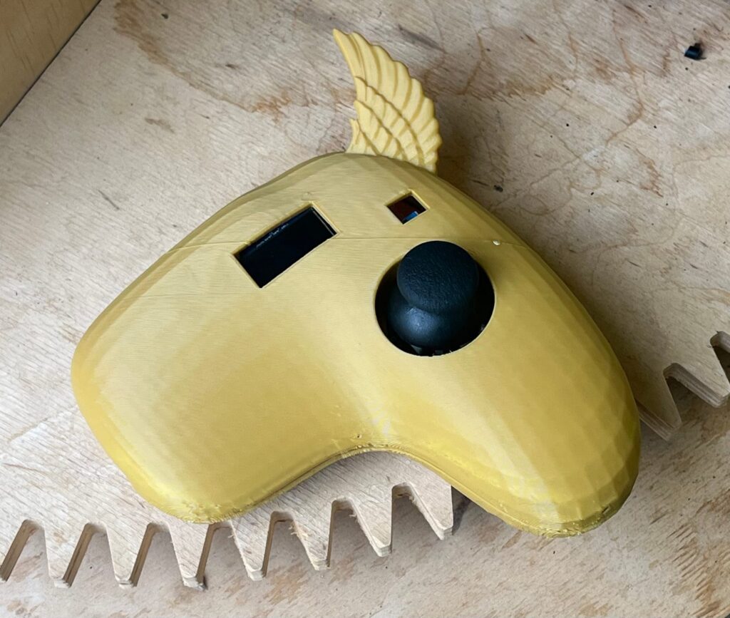
At the end of Fab Academy I wrote that I was "waiting for Joystick v2". Here it is! 🎮 It is very close to my old joystick. There are only two differences:
- The board: on my old board the SDA and SCL pins of the OLED screen were swapped. On the new board the only change is that these two pins are now in the right places.
- The case: I only added a small piece of a bird wing to the outside. 😄
Here is the final joystick, inside and outside:
A power switch that saves the battery
I wanted the switch to really turn the joystick off. The problem: my switch is on D6 (GPIO21), and on the ESP32-C3 only GPIO0–5 can wake the chip from deep sleep.
So the joystick uses light sleep. When I switch it OFF, it first tells the car "stick released" (so the car stops), shows OFF for a moment, and turns off the screen, the LED and the radio. When I switch it ON, it restarts and finds its car again in about a second.
If the switch works the other way round on your board, change one line: POWER_OFF_LEVEL from LOW to HIGH.
What the joystick shows
- Setup: "PRESS SW to start" on Joystick 1, "GET READY" on Joystick 2
- Playing: the timer, both scores, my 4 tags as circles, and the battery. In the last 30 seconds the timer blinks.
- Team win: our time and a happy face
- Game over: how many tags we found and a sad face
- No link: the joystick can't find its car
The LED on the joystick blinks every time my car finds one of my tags.
| Joystick pin | Used for |
|---|---|
| D0 / D1 | Stick X / Y |
| D2 | Battery (100 kΩ / 100 kΩ divider) |
| D3 | SW button (press the stick) |
| D4 / D5 | OLED SDA / SCL (swapped on my old board) |
| D6 | Power switch |
| D10 | LED |
5. The New Car
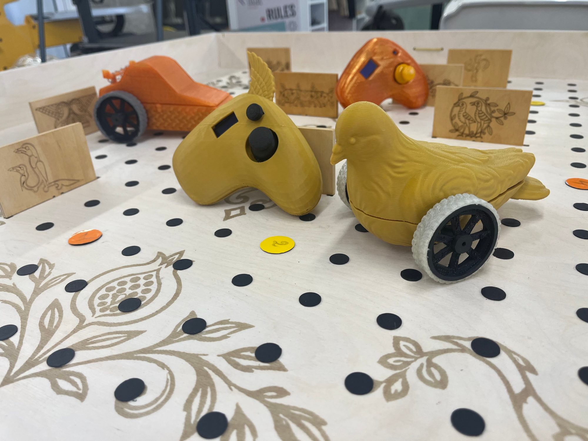
The new car is the second car of the game: the yellow car, Player 2. My Fab Academy car became the orange car, Player 1.
My game is called Maze of Birds, so this time I decided to give the new car a bird design. 🐦
Step 1: The bird body and the wheels
I didn't want to spend a lot of time on a completely new design, so I downloaded a bird model from the internet [dove-stl] (https://cults3d.com/en/3d-model/art/dove-stl-realistic-dove-3d-model-bird-sculpture-for-3d-printing) and started working on it in Blender.
I used the same Blender functions as for my previous car:
- I cut the bird's body in the middle into two parts.
- I gave the body thickness.
- I made the right holes to place the PCB and the NFC reader safely inside the body.
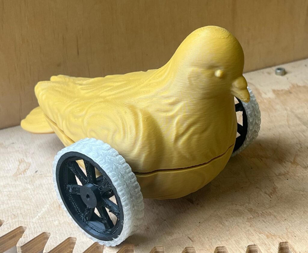
I printed the final body in yellow PLA.
For the wheels I also tried something new. On my old car I sprayed silicone on the outside of the wheels to get more grip on the wood. This time I printed the outer rim of the wheel separately, in TPU filament.
Here is the final car from the outside:
Step 2: One battery and no voltage regulator
There are many changes on the PCB. On my old car I used three 4.2 V Li-ion batteries. For the new car I decided to use one 3.7 V 2000 mAh battery, so the car is lighter and more compact.
With a 3.7 V battery I don't need a voltage regulator anymore:
- The battery goes straight to the battery pads under the XIAO ESP32-C3, so it also charges through the XIAO's USB-C port.
- The XIAO reads the battery voltage on D1. On my first schematic it was on D10, but D10 can't read analog voltages.
Step 3: My own motor driver from MOSFETs
My old car uses two A4953 motor drivers, but the A4953 needs at least 8 V to switch on. With one 3.7 V battery, the motors would never turn. The other motor driver in our lab, the TB67H451, needs at least 4.5 V, so it couldn't work either. One option was a boost module that makes 9 V for the A4953s, but I decided to build the motor driver myself, from MOSFETs.
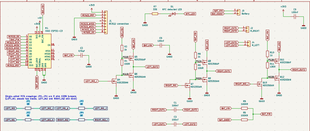
Each motor gets its own H-bridge. An H-bridge has two sides, one for each motor wire, and each side is the same small circuit:
- a P-channel MOSFET that connects the motor wire to the battery +
- an N-channel MOSFET that connects the motor wire to GND
- a small N-channel MOSFET and two resistors that let one XIAO pin switch the other two. Pin HIGH: the motor wire goes to +. Pin LOW: the motor wire goes to GND.
So each motor uses two XIAO pins:
| IN1 | IN2 | Motor |
|---|---|---|
| HIGH | LOW | Forward |
| LOW | HIGH | Backward |
| LOW | LOW | Stop |
Speed works with PWM: the code switches the pin on and off very fast, and the longer the pin is on, the faster the motor turns. For two motors, I need 4 of these sides: 12 MOSFETs (4 P-channel and 8 N-channel) and 8 resistors.
Step 4: The PCB
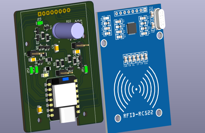
I drew the schematic in KiCad. The board is 48 × 60 mm, single-sided, so I can mill it like my other boards. The RC522 NFC reader sits on the front of the board.
What I learned while making it:
- A bug in my schematic! Both H-bridges used the same labels (PG1A, NG1A, PG1B, NG1B), so KiCad connected them together. Both motors would always turn the same way, and the car could never turn. 💀 Renaming the second bridge's labels to PG2A, NG2A, PG2B, NG2B fixed it.
- 0 Ω jumpers: on one copper layer some wires of the two H-bridges have to cross, so the board has four 0 Ω resistors (JP1–JP4) that work as bridges.
- Ground: the battery minus goes straight to the motor ground, so the motor current doesn't flow through the XIAO.
Here are two images from KiCad:
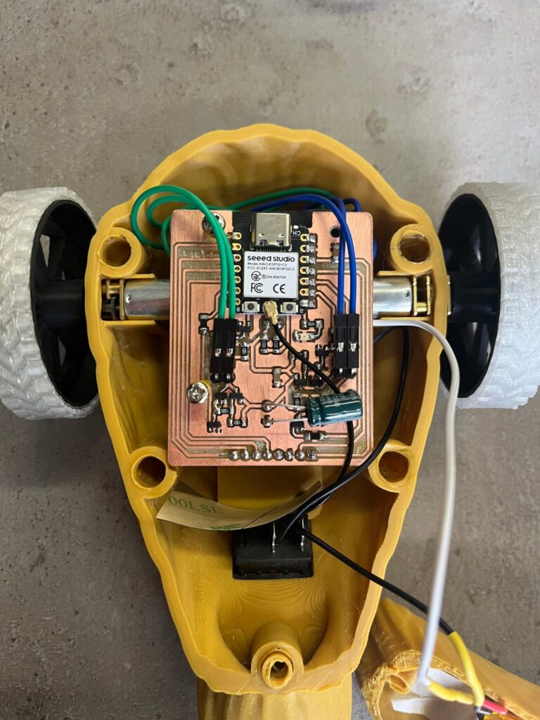
And here is my final birdie-car from inside. 😍
Step 5: Making the car slower
The new car was too fast for a maze with 100 mm cells. I changed two lines in Player2Car.ino:
#define MAX_SPEED  120   // driving speed (255 = full power)
#define TURN_SPEED  80   // turning speed (lower = slower turns)
Now it is much easier to drive. Much lower values are not a good idea: below about 100 the motors may only hum and not move, especially when the battery is low.
Old car and new car: the differences
| Old car (Fab Academy) | New car | |
|---|---|---|
| Player | Player 1 (orange) | Player 2 (yellow) |
| Body | Blender, a box with motor and PCB panels | Bird model, edited in Blender, yellow PLA |
| Wheels | Silicone sprayed on the outside | Separate TPU rim |
| Board | RC-V.0.3 | MazeOfBirds-Car, 48 × 60 mm, single-sided |
| Motor driver | 2 × A4953 | 2 H-bridges built from MOSFETs |
| Motors | 2 × N20, 12 V, 500 RPM | 2 × N20, 3 V, 660 RPM |
| Battery | 3 × 4.2 V Li-ion | 1 × 3.7 V, 2000 mAh |
| Voltage regulator | LM2940, 5 V | Not needed |
| Battery check | – | On D1 |
| Speed in the code | MAX_SPEED 200 | MAX_SPEED 120, TURN_SPEED 80 |
| Code | Player1Car.ino | Player2Car.ino |
Because the boards are different, the pins are different too, so each car has its own code:
| Signal | Old car (Player 1) | New car (Player 2) |
|---|---|---|
| NFC SS / SCK / MOSI / MISO / RST | D5 / D7 / D10 / D9 / D8 | D0 / D2 / D3 / D4 / D10 |
| Right motor IN1 / IN2 | D1 / D0 | D6 / D5 |
| Left motor IN1 / IN2 | D4 / D3 | D9 / D8 |
| NFC LED | D6 | D7 |
| Battery | – | D1 |
6. The Wio Terminal: a New Maze Every Round
In Fab Academy my maze was random too, but it was made in OpenSCAD (RandomMaze.scad), so I needed a computer to see a new maze. Now the Wio Terminal creates the maze itself, with the same idea, and shows it on its screen. You build it on the board and play.
This picture shows how the Wio builds a maze:
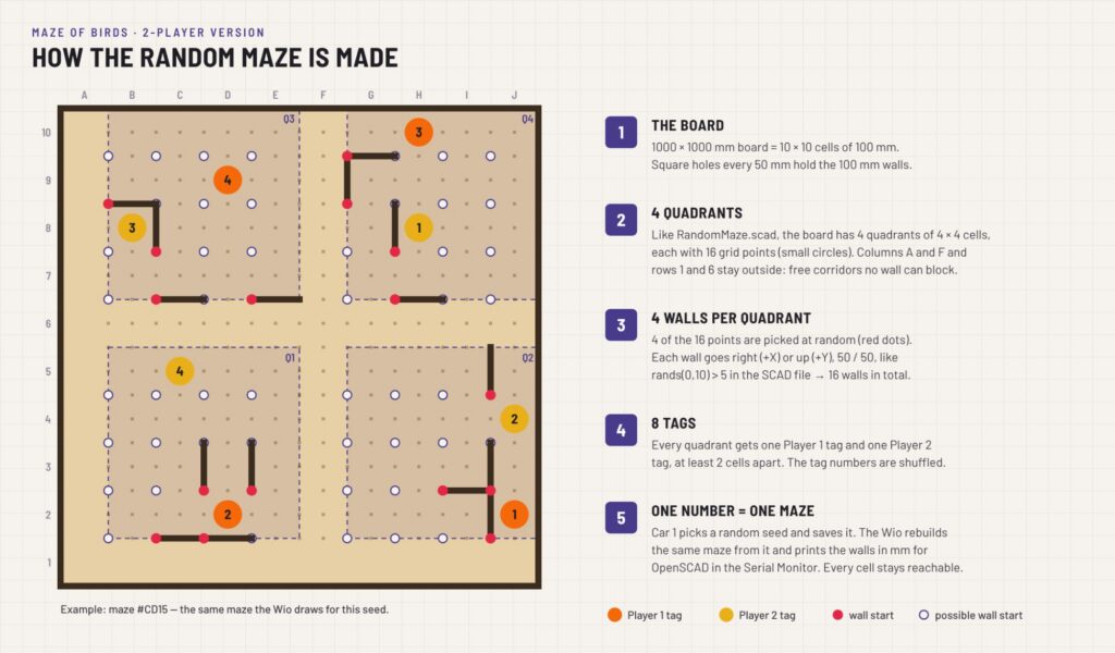
How the maze is made:
- The board is 1000 × 1000 mm, which makes 10 × 10 cells of 100 mm. It has 4 quadrants of 4 × 4 cells, like in my SCAD file. Columns A and F and rows 1 and 6 are free corridors.
- In each quadrant, 4 walls are placed at random, so there are 16 walls in total.
- Each wall goes right or up, 50 / 50, like
rands(0,10,1)[0] > 5in OpenSCAD. - Each quadrant gets one orange tag and one yellow tag, at least 2 cells apart.
On the screen the board has columns A–J and rows 1–10, so it is easy to find where each wall and tag goes. The Wio also prints the maze in the Serial Monitor, with the wall positions in millimetres for OpenSCAD.
// ControlWith-WIOTerminal.ino: 4 random walls in every quadrant
for (int k = 0; k < WALLS_PER_QUADRANT; k++) {
  Wall& w = walls[n++];
  w.x = QX[q] + pts[k] / 4;            // one of the 16 points of this quadrant
  w.y = QY[q] + pts[k] % 4;
  w.horizontal = (rnd() >> 31) & 1;    // like rands(0,10,1)[0] > 5
}
The maze comes from one number (the seed). Car 1 keeps it in its memory, so if the Wio or a car restarts, the same maze comes back. The generator was tested with 20,000 random mazes, and in all of them every cell could be reached. 😍
| Wio button | What it does |
|---|---|
| Top-left [L] | New maze (before a game, or after it) |
| Top-right [R], hold 2 seconds | Stop a running game (the maze stays) |
7. How the Five Devices Work Together
The game has 5 devices: 2 cars, 2 joysticks and the Wio Terminal.
This picture shows which device talks to which: 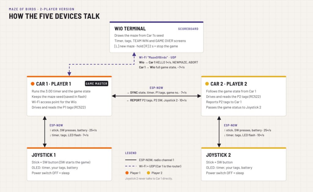
Components and wiring
- Car 1 (my old car) is the game master. It has the only clock (3:00), knows the score of both players, decides TEAM WIN or GAME OVER, and keeps the maze number. It also creates the Wi-Fi network MazeOfBirds for the Wio.
- Car 2 (the new bird car) follows Car 1. It reads the yellow tags and sends them to Car 1.
- The joysticks send the stick, the button and the battery level to their own car 25 times per second.
- The Wio Terminal connects to Car 1 over Wi-Fi and shows everything.
The cars and joysticks talk with ESP-NOW (the same as in my Fab Academy project), all on radio channel 1.
What I learned about making it reliable
- Every message is sent many times per second, so if one is lost, nothing happens.
- Tags travel as a list, not a number, so the Wio knows which tags were found, and a tag can never count twice.
- The joystick counts button presses instead of sending "pressed / not pressed". Short presses are never lost, and a joystick that restarts doesn't start a game by itself.
- Safety stops: a car stops if its joystick is silent for half a second.
Programming
- Cars and joysticks: Arduino IDE, esp32 by Espressif (version 3.x), board XIAO_ESP32C3. Libraries: MFRC522, Adafruit SSD1306, Adafruit GFX.
- Wio Terminal: Seeed SAMD Boards, board Seeed Wio Terminal. Libraries: Seeed_Arduino_rpcWiFi and Seeed_Arduino_LCD.
- Both joysticks use the same code. Only
PLAYER_IDand the address of the car are different.
Before the first game:
- Upload each joystick and copy
THIS JOYSTICK MACfrom the Serial Monitor into its car's code (JOY1_MACorJOY2_MAC). - Put the IDs of each player's 4 tags into
coinTagsof the right car. The first line is tag 1, the second is tag 2, and so on. - Switch on Car 1 first, because it creates the Wi-Fi for the Wio.
Settings you can change
| What | Where | Setting |
|---|---|---|
| Game time | Player1Car.ino | GAME_TIME_SEC 180 |
| Car speed | each car | MAX_SPEED, TURN_SPEED |
| Player 2 can also start | Player1Car.ino | P2_CAN_START 1 |
| Walls per quadrant | Wio | WALLS_PER_QUADRANT 4 |
| Sound on / off | Wio | SOUND_ON |
| Joystick switch direction | each joystick | POWER_OFF_LEVEL |
8. Getting Started: How to Play
- Build the maze. Look at the Wio and put the 16 walls and the 8 tags in their places.
- Get ready. The Wio shows a green dot for each connected device.
- Start. Player 1 presses the joystick button (press the stick down). 3:00 starts!
- Collect your tags. Drive over your own tags. Each one makes the LEDs blink, the Wio beeps, and the tag on the map gets a check mark.
- Help your friend. When you have 4/4, your car stops and you guide the other player.
- The end. Both 4/4 in time means TEAM WIN. Time over means GAME OVER, and the Wio shows which tags were missing.
- Play again. Player 1 presses the button again, and a new maze appears.
Here is one round of the game in one picture: 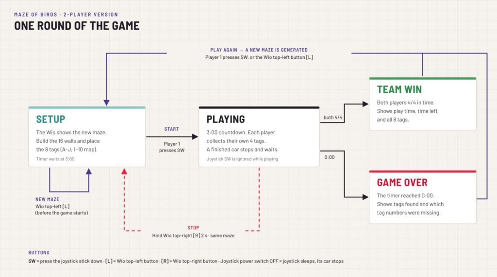
9. Materials and Tools
Materials
- Game board 1000 × 1000 mm, plywood, with wall holes, engraved and varnished
- 16 maze walls, 100 mm, plywood, engraved and varnished, plus the outer frame
- Wood varnish
- Old car (Player 1): RC-V.0.3 board, XIAO ESP32-C3, 2 × A4953, 2 × N20 12 V motors, RC522, 3 Li-ion batteries
- New car (Player 2): MazeOfBirds-Car board, XIAO ESP32-C3, 12 MOSFETs (4 P-channel, 8 N-channel), 8 resistors, 4 × 0 Ω jumpers, 2 × N20 3 V 660 RPM motors, RC522, 3.7 V 2000 mAh battery
- New car body: yellow PLA, wheel rims in TPU
- 2 joysticks: joystick board, XIAO ESP32-C3, KY-023 stick, SSD1306 OLED, Li-ion battery, power switch
- Seeed Wio Terminal + USB-C cable or power bank
- 8 NTAG213 NFC stickers: 4 orange and 4 yellow, numbered 1–4
Tools
- Laser cutter for the engraving
- CNC router for the game board
- PCB milling machine
- 3D printer for the car bodies, wheels and joystick cases (PLA, PETG, TPU)
- Soldering station
- Inkscape, KiCad, Blender, OpenSCAD and Arduino IDE
10. Problems and What I Learned
- "No device found on ttyACM0". The Wio code compiled, but it wouldn't upload. The fix: slide the Wio power switch down twice quickly. The blue LED starts breathing, then choose the new port and upload again.
- A motor driver needs the right voltage. The A4953 needs at least 8 V, so it can't run from one 3.7 V battery. That is why I built my own H-bridges from MOSFETs.
- Labels in KiCad connect wires. Two H-bridges with the same labels became one, and both motors would always turn together. Now I check my labels twice!
- Not every pin can read a voltage. D10 on the XIAO ESP32-C3 can't read analog values, so the battery check moved to D1.
- Swapped SDA and SCL on my old joystick board. On the new board they are in the right places.
- The new car was too fast. See Step 5 of the new car:
MAX_SPEED 120andTURN_SPEED 80. - The car froze when it found a tag. In my old code the LED blinked with
delay(), so for almost half a second the car didn't listen to the joystick, while its motors kept going. Now the LED blinks without stopping the car. - Accidental restarts. Any button press restarted the game. Now only Player 1 starts, the button does nothing during a game, and to stop a game you hold the Wio button for 2 seconds.
- The Wio screen flickered because it redrew everything every second. Now it only redraws what changed.
- Too many walls. When I first moved my SCAD maze to the Wio, it put a wall on every grid point: 64 walls! I changed it to 4 walls per quadrant (16 walls), which is much faster to build before every round.
- Deep sleep doesn't work on every pin. Only GPIO0–5 can wake an ESP32-C3 from deep sleep. On my next joystick board I will put the power switch on one of those pins.
I rewrote the code of all five devices with the help of Claude (an AI assistant). Before testing on the real board, we tested the game logic in a computer simulation: start, tags, win, play again, stop, time over, lost connection and the power switch.
11. Result
Here are some videos of a full game:
What's next
Honestly, right now I don't have new ideas for how to continue this game. 😄
12. Files and Credits
All the code and the diagrams are in maze-of-birds-2.zip: the five Arduino sketches (Player1Car, Player2Car, Player1Joystick, Player2Joystick, ControlWith-WIOTerminal) and the images from this page.
My Fab Academy documentation, with the KiCad, Blender and OpenSCAD files: Maze of Birds, Fab Academy 2026.
Made by Mariam Daghbashyan at Fab Lab Armenia.
License: CC BY-NC-SA 4.0
More photos & videos