Assignment for this week:
Group assignment:Compare the performance and development workflows for other architectures.
Individual assignment:Read a microcontroller data sheet. Program your board to do something, with as many different programming languages and programming environments as possible.
- IntroductionThis week I am supposed to make a board and programm it to do something. Due to the situation with COVID19 I lab was closed and I didn’t have access to the lab. I had a kit prepared by my instructor and started to work with Arduino uno, breadboard and some available components. It gave me experience in working with electrical circuits as well as I started to explore deeper the basics of electronics and board programming in Arduino IDE.
Hopefully we will be out of quarantine before the end of this Fab Academy cycle and I will design, make and program my own PCB.
- IntroductionThis week I am supposed to make a board and programm it to do something. Due to the situation with COVID19 I lab was closed and I didn’t have access to the lab. I had a kit prepared by my instructor and started to work with Arduino uno, breadboard and some available components. It gave me experience in working with electrical circuits as well as I started to explore deeper the basics of electronics and board programming in Arduino IDE.
- What is Arduino? There are many sources where it is possible to get information about Arduino and find many tutorials there. This one is for complete beginners and was very helpful for me. The official website is very helpful as well. Here you can find everything about Arduino: tutorials, very good forums, etc. According to the Official website “Arduino is an open-source electronics platform based on easy-to-use hardware and software. Arduino boards are able to read inputs – light on a sensor, a finger on a button, or a Twitter message – and turn it into an output – activating a motor, turning on an LED, publishing something online. You can tell your board what to do by sending a set of instructions to the microcontroller on the board. To do so you use the Arduino programming language (based on Wiring), and the Arduino Software (IDE), based on Processing.”
So, Arduino is a programming language, an open source PCB and also a Software based on Processing.
Arduino open source PCBs contain a microcontroller which is able to be programmed to sense and control objects in the physical world. By responding to sensors and inputs, the Arduino is able to interact with a large array of outputs such as LEDs, motors and displays. Since the board is open-source, it allows anyone to produce their own board. There are hundreds of Arduino compatible clones and variations available with different names for example LilyPad board from Sparkfun. One of the best reasons to buy a clone is the fact they are generally less expensive than their official counterpart. If you are going to buy a cloned board make sure that the seller is reliable. Here you can find a comparison Guide for different types of Arduino boards.Arduino programming language is based on Wiring and can be divided in three main parts: functions, values (variables and constants), and structure. Functions are for controlling the Arduino board and performing computations. More detailed information and full guide to the Arduino programming language you can find in this page.
Arduino has a web editor as well, so you can program board without downloading anything.Arduino Software (IDE) is an open-source Software which makes it easy to write code and upload it to the board. It runs on Windows, Mac OS X, and Linux. The environment is written in Java and based on Processing and other open-source software. Here you can find a full guide for Arduino IDE software.
- Arduino UnoAs it says on the Arduino Uno website: the Arduino UNO is the best board to get started with electronics and coding. If this is your first experience tinkering with the platform, the UNO is the most robust board you can start playing with. The UNO is the most used and documented board of the whole Arduino family.
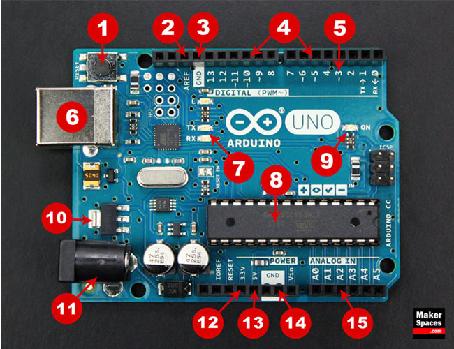
I used Arduino Uno and the first step was to understand what components it has.. Here is the board breakdown for Arduino Uno (Image credit Makerspaces.com ).
From the sources below you can find Atmega8 microcontroller datasheets.
– Datasheet summary
– DatasheetHere is the Arduino Uno REV3 Schematic and a full guide to it.
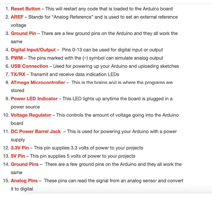
I will try to explain definitions and usage of the pins on Arduino Uno REV3 microcontroller.
- GND – In the Arduino Uno pinout, you can find 5 GND pins, which are all interconnected. The GND pins are used to close the electrical circuit and provide a common logic reference level throughout your circuit.
- VIN Pin – This pin is used to power the Arduino Uno board using an external power source. The board can be powered by 5-20 volts but the manufacturer recommends to keep it between 7-12 volts. Above 12 volts, the regulators might overheat, and below 7 volts, might not suffice.
- 5V and 3.3V – they provide regulated 5 and 3.3V to power external components according to manufacturer specifications.
- RESET – this pin resets the program. Usually you take this pin low to reset the controller.
- AREF – AREF means Analogue REFerence. It allows us to feed the Arduino a reference voltage from an external power supply.
- IOREF – This pin is the input/output reference. It provides the voltage reference with which the microcontroller operates.
- A0-A5 – Analog inputs, where SDA and SCL are the two pins of the Inter-Integrated Circuit (I2C) bus:
- SDA – Serial Data
- SCL– Serial Clock
- Pins 0-13 of the Arduino Uno serve as digital input/output pins. Pin 13 of the Arduino Uno is connected to the built-in LED.
- In the Arduino Uno – pins 3,5,6,9,10,11 have PWM capability.
Pulse Width Modulation (PWM) is a modulation technique used to encode a message into a pulsing signal. A PWM is comprised of two key components: frequency and duty cycle. The PWM frequency dictates how long it takes to complete a single cycle (period) and how quickly the signal fluctuates from high to low. The duty cycle determines how long a signal stays high out of the total period. Duty cycle is represented in percentage. - Serial Peripheral Interface (SPI) is a serial data protocol used by microcontrollers to communicate with one or more external devices in a bus-like connection. The SPI can also be used to connect 2 microcontrollers. On the SPI bus, there is always one device that is denoted as a Master device and all the rest as Slaves. In most cases, the microcontroller is the Master device.
- SPI – SS/SCK/MISO/MOSI pins are the dedicated pins for SPI communication. They can be found on digital pins 10-13 of the Arduino Uno.
- MISO (Master In Slave Out) – A line for sending data to the Master device
- MOSI (Master Out Slave In) – The Master line for sending data to peripheral devices.
- SCK (Serial Clock) – A clock signal generated by the Master device to synchronize data transmission.
- SS (Slave Select) – Determines which device the Master is currently communicating with.
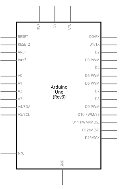
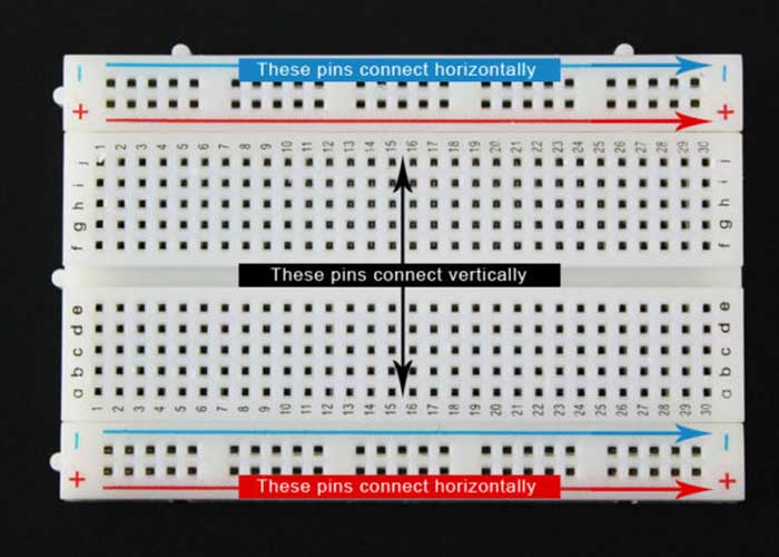
- Arduino BreadboardAs I was quarantined and the lab was closed, I couldn’t make my own board and had to use an Arduino solderless breadboard. This device allows you to prototype your Arduino project without having to permanently solder the circuit together. Using a breadboard allows you to create temporary prototypes and experiment with different circuit designs. Inside the holes (tie points) of the plastic housing, are metal clips which are connected to each other by strips of conductive material (Image credit Makerspaces.com ).
I used different types of jumper wires to connect components on the breadboard to the Arduino. You may need 3 types of wires:- Male to male
- Male to female
- Female to female
The difference between each is in the end point of the wire. Male ends have a pin protruding and can plug into things, while female ends do not and are used to plug things into. Male-to-male jumper wires are the most common and what you likely will use most often. When connecting two ports on a breadboard, a male-to-male wire is what you’ll need. More about types and usage of jumper wires you can find in this website
- Blinking the built-in LED on ArduinoThe first project I run on Arduino was the blinking of the built-in LED on it. For that I did the following steps:
- Download Arduino IDE from the official website. We need the application to write a program and program the board.
- Connect Arduino Uno to the computer via USB cable.
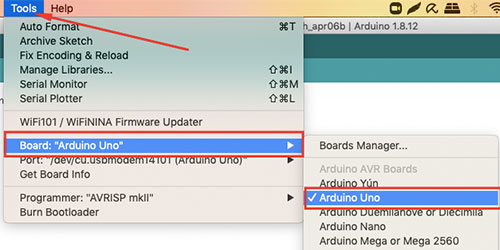
- Open Arduino IDE, go to Tools – Board and check Arduino Uno
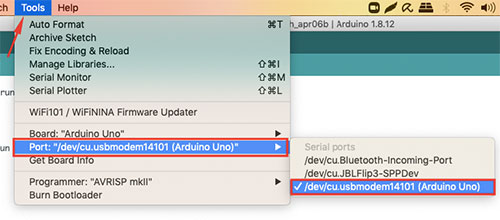
- Go to Tools – Port and check the proper port. Usually it starts with “usb….”
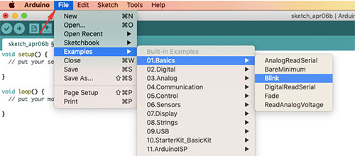
- Open File – Examples -Basics- Blink . Here you can find already written code for blinking the built-in LED.
- I changed the delay for the time when LED is on to 5000ms which is 5 seconds and delay for the LED off to 1second.
// the setup function runs once when you press reset or power the board void setup() { // initialize digital pin LED_BUILTIN as an output. pinMode(LED_BUILTIN, OUTPUT); } // the loop function runs over and over again forever void loop() { digitalWrite(LED_BUILTIN, HIGH); // turn the LED on (HIGH is the voltage level) delay(5000); // wait for five seconds digitalWrite(LED_BUILTIN, LOW); // turn the LED off by making the voltage LOW delay(1000); // wait for a second }- Then press Upload. It will take some time and you will see a message “Avrdude is done”
Here is the result.
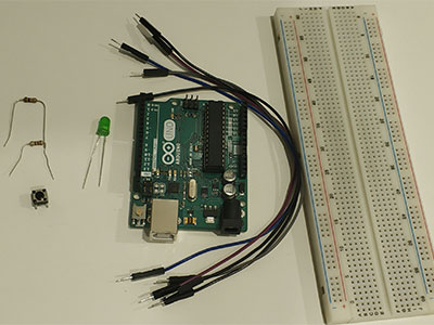
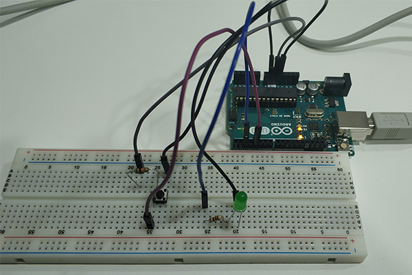
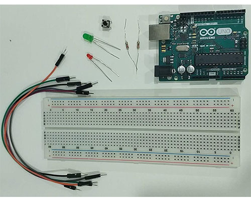
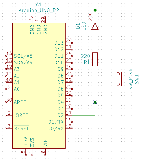
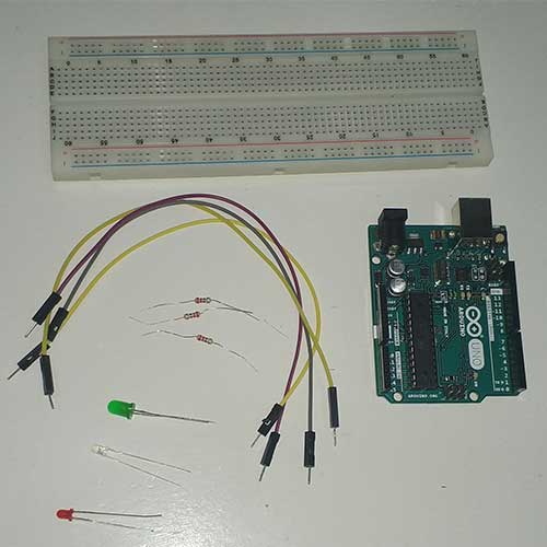
- Push Button and LED control with the ArduinoAfter programming Arduino Uno to blink the internal LED, I started to work on the simplest circuit with a breadboard: controlling LED with push button. I can’t say that I was confident enough to do everything myself, so I watched tutorials for that. For this project we need:
- Arduino Uno with USB cable
- Arduino breadboard
- 5 Male to male wires
- LED
- Push button
- 220Ohm resistor
- 10kOhm resistor
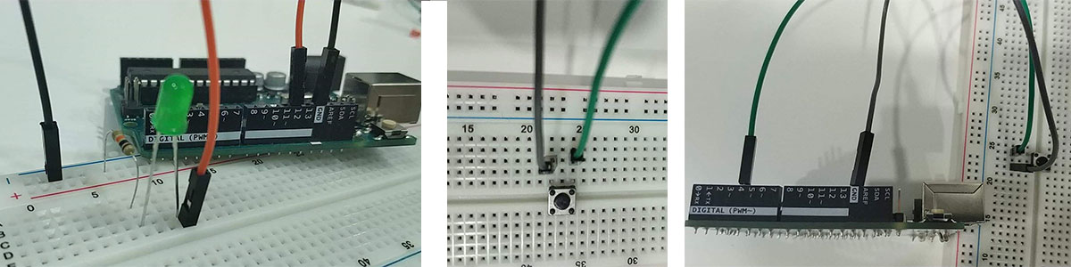
Here are the steps for making the circuit and programming:
- Connect LED on one of the horizontal lines of Arduino Uno. Remember – LED (Light-emitting diode) is a diode, therefore the direction for connection matters. It has short and long legs. The Short leg is called Cathode (-) and the long leg is called Anode (+).
- Connect 220 ohm resistor to the LED’s long leg (anode +). We need to have a resistor along with LED, to prevent it from high current and burning.
- Connect the resistor’s other leg to the digital pin 2 on Arduino using a wire.
- Connect the LED’s short (cathode -) leg to the Ground on Arduino using a wire.
- Attach button to the board
- Connect the 10kohm resistor to the button’s bottom leg. We need to connect a resistor to the button to prevent “floating”. When the button is connected without a resistor and the button pressed, pin 2 is connected through the switch to the Arduino’s 5V power source. But when the button isn’t pressed, pin 2 isn’t connected to anything. We say that it’s floating. It might be HIGH or it might be LOW – there’s no predicting. So we need to make sure pin 2 goes LOW when the switch isn’t pressed. To do that, we use something called a pull-down resistor. Connect a high value resistor to the switch output and a wire from the resistor to ground
- Connect the 10 kom resistor’s other leg to the Ground on Arduino using a wire.Connect button’s other bottom leg to to the 5V on Arduino using a wire.
- Connect button’s top leg to to the digital pin 4 on Arduino using a wire
- Upload the following code to the board using Arduino IDE
const int ledPin = 2;
const int buttonPin = 4;
int buttonState = 0;
void setup() {
 // put your setup code here, to run once:
 Serial.begin(9600);
 pinMode(ledPin, OUTPUT);
 pinMode(buttonPin, INPUT);
}
void loop() {
 // put your main code here, to run repeatedly:
 buttonState = digitalRead(buttonPin);
 if (buttonState == HIGH) {
 digitalWrite(ledPin, HIGH);
 Serial.println("LED ON");
 }
 else {
 digitalWrite(ledPin, LOW);
 Serial.println("LED OFF");
 }
}
As a result I had an LED with button control.
The original file with the code: Push Button and LED control
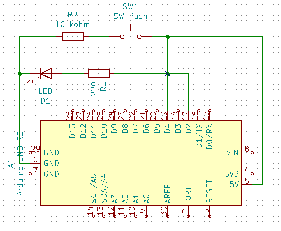
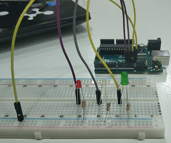
The original file with the schematic: Push Button and LED control schematic - Push Button and LED control using a built-in pull-up resistor of ArduinoI did the previous project using an external pull-up resistor. But later on I found out that there are 20K pullup resistors built into the Arduino Uno Atmega chip that can be accessed from software. These built-in pullup resistors are accessed by setting the pinMode() as INPUT_PULLUP. When connecting a sensor to a pin configured with INPUT_PULLUP, the other end should be connected to ground. In the case of a simple switch, this causes the pin to read HIGH when the switch is open, and LOW when the switch is pressed. After discovering the information above, I made one more circuit with a push button and 2 LEDs, this time using the built-in pull-up resistor in the Arduino. We need following components for that:
- Arduino Uno with USB cable
- Arduino breadboard
- 5 x Male to male wires
- 2 x LEDs
- Push button
- 2 x 220Ohm resistors
Here are the steps for making the circuit and programming:
- Connect the Ground pin of Arduino to the negative rail on the breadboard using a wire. By doing this we will have a common ground.
- Connect one leg of 220ohm resistor to the negative rail and the other leg vertically down.
- Connect LED horizontally. LED’s short leg (-) should be connected to the resistor’s leg.
- Connect LED’s long (+) leg to the digital pin 12 on the Arduino.
- Repeat this for the other LED as well, connect the second LED’s anode to the digital pin 13 on the Arduino.
- Attach the push button to the breadboard.
- Connect one of the legs of the push button to the Ground of arduino.
- Connect another leg of the push button to the digital pin 4 on the Arduino. This will be set up as an INPUT_PULLUP and will use the internal resistor.
- Connect Arduino to the computer using USB cable.
- Upload the following code to the board using Arduino IDE.
const int ledPin1 = 12;
const int ledPin2 = 13;
const int buttonPin = 4;
int buttonState = 0;
void setup() {
// put your setup code here, to run once:
 Serial.begin(9600);
 pinMode(ledPin1, OUTPUT);
 pinMode(ledPin2, OUTPUT);
 pinMode(buttonPin, INPUT_PULLUP);
}
void loop() {
// put your main code here, to run repeatedly:
buttonState = digitalRead(buttonPin);
if (buttonState == LOW) {
delay(100);
digitalWrite(ledPin1, HIGH);
digitalWrite(ledPin2, LOW);
Serial.println("LED1 ON");
}
else {
delay(100);
digitalWrite(ledPin2, HIGH);
digitalWrite(ledPin1, LOW);
Serial.println("LED2 ON");
}
}
Here is the result:
The original file with the code: Push Button and LED control without external resistor
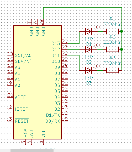
The original file with the schematic: Push Button and LED control without external resistor, schematic - Sequential turning on and off for 3 LEDsFor running this project I followed this tutorial and slightly changed the code. In this project I constructed a board with 3 LEDs of different colors and programmed them to go on and off with some delay. Here are the components that we need:
- Arduino with the USB cable
- Arduino breadboard
- 3 LEDs
- 3 220ohm resistors
- 4 Male to Male wires
Here is the step by step instruction:
- Connect the Ground pin of Arduino to the negative rail on the breadboard using a wire. By doing this we will have a common ground.
- Connect 220ohm resistors to the board vertically in a way that one leg is connected to the negative rail.
- Now connect LEDs horizontally. We should connect LED’s negative (short) leg to the resistor.
- Connect LEDs’ positive legs to the Arduino digital pins 11, 12, 13 accordingly.
- Connect the Arduino to the computer and upload the following program to the board.
int LED1 = 13;
int LED2 = 12;
int LED3 = 11;
void setup() {
 pinMode(LED1, OUTPUT);
 pinMode(LED2, OUTPUT);
 pinMode(LED3, OUTPUT);
}
void loop() {
 digitalWrite(LED1, HIGH); // turn on LED1
 delay(200); // wait for 200ms
 digitalWrite(LED1, LOW); // turn off LED1
 delay(100);
 digitalWrite(LED2, HIGH); // turn on LED2
 delay(200); // wait for 200ms
 digitalWrite(LED2, LOW); // turn off LED2
 delay(100);
 digitalWrite(LED3, HIGH); // turn on LED3
 delay(200); // wait for 200ms
 digitalWrite(LED3, LOW); // turn off LED3
 delay(100); // wait for 100ms before running program all over again
}
Here is the result.
The original file with the code: Sequential turning on and off for 3 LEDs, code
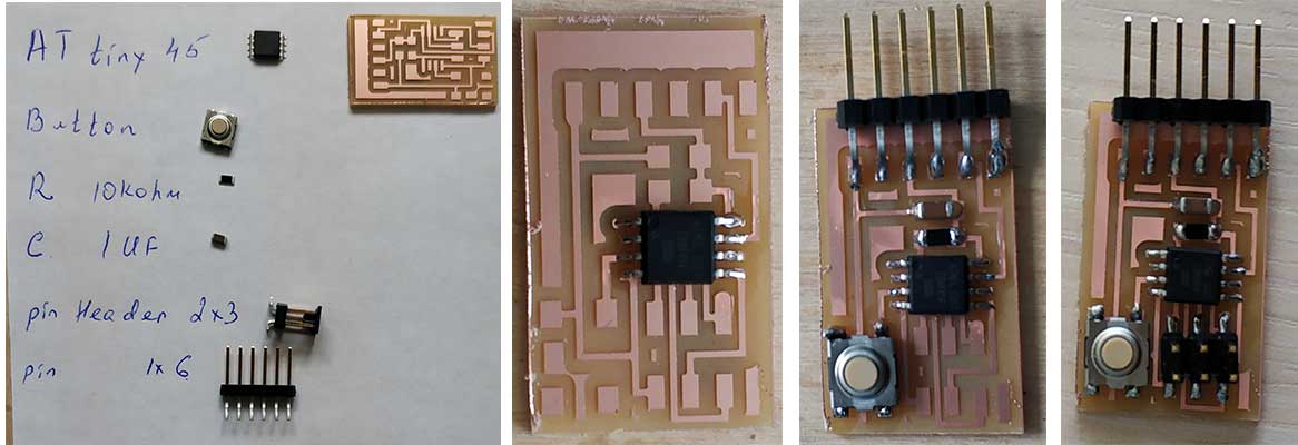
The original file with the schematic: Sequential turning on and off for 3 LEDs, schematic - Programming Hello.button.45When we were out of quarantine, I started to do missed assignments from electronics. As we didn’t have much time, we were allowed to cut one of Neil’s boards rather than design our own ones. I have decided to make the hello button45 board because I’m going to have a button on my final project and it would be nice to have experience beforehand.
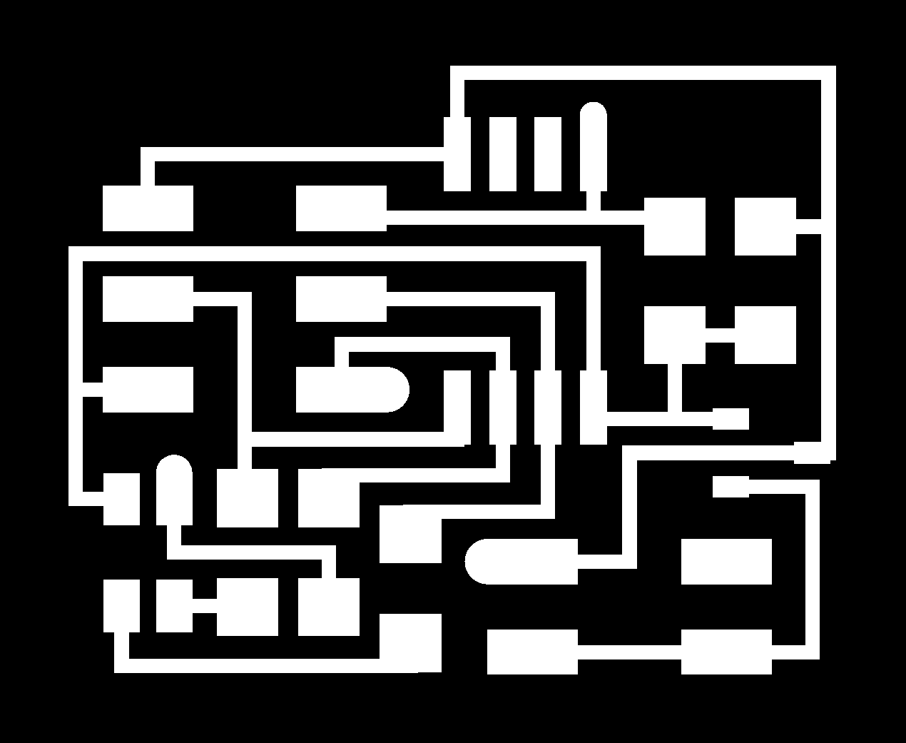
First of all I downloaded images for traces and interior of the board and generated G codes in fabmodules.org.


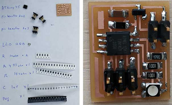
Then I did milling the board and started assembling it.
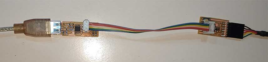
To do the programming I need to connect the board to fab ISP using a USB cable and to the computer, using a FTDI cable.
Then download C code and make file from the keynotes. Also, as I’m going to use the serial monitor, I need the term.py file.
After downloading them and locating in one folder, I started programming by running the following codes:
make -f hello.button.45.make
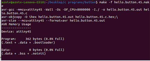
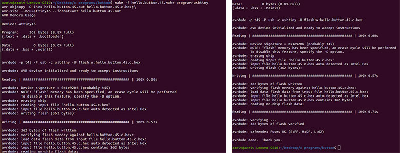
make -f hello.button.45.make program-usbtiny
If everything goes well we should open the serial monitor by running the command
python term.py /dev/ttyUSB0 9600
Here ttyUSB0 is the port where your FTDI cable is connected to and 9600 is the serial monitor baud. This should be the same as in the C code.
I had a problem with running the serial monitor and was constantly getting an error that tkinter file can not be imported. I found good documentation from a previous year’s student Nicolo Gnecci where the similar problem was described and solved. I have tried almost everything but it didn’t work again.
Then I found the issue described in Stackoverflow and found out that in the Python code there is a line which should be different depending on your Python version. It says that the Tkinter module is named Tkinter (capital “T”) in python 2.x, and tkinter (lowercase “t”) in python 3.x.
As I have python 2, I just changed the lowercase “t” to uppercase in the code and it worked.
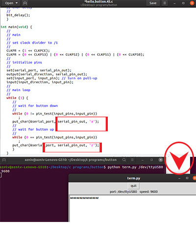
Basically, it types letter “b” on the serial monitor, when button is pressed and letter “u”, when button is being released. I found that part of the code and changed the letters to “a” and “z”. - Programming Hello RGB LEDWhen we were out of quarantine, I started to do missed assignments from electronics. As we didn’t have much time, we were allowed to cut one of Neil’s boards rather than design our own ones. I have decided to make the hello RGB LED board.
First of all I downloaded images for traces and interior of the board and generated G codes in fabmodules.org.

Then I did milling the board and started assembling it.
To do the programming I need to connect the board to fab ISP using a USB cable.
Then download C code and make file from the keynotes. After downloading them and locating in one folder, I started programming by running the following codes:
make -f hello.RGB.45.make
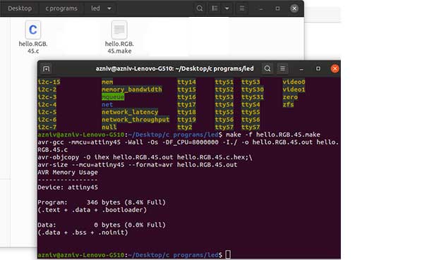
make -f hello.RGB.45.make program-usbtiny
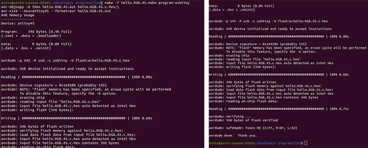
When I connected the board to 9V battery it started to change colors but the green one was never on. So I checked the connections with the multimeter and found out that there is problem with soldering of the LED and the leg fr green is not connected. So I fixed that.
After making sure that board is working I started to play with different arguments: changing color patterns and delay time. It gives the possibility to receive different colors by turning on and off some red, green blue colors. Having the RGB color chart. helps to find the proper combination for desired color.
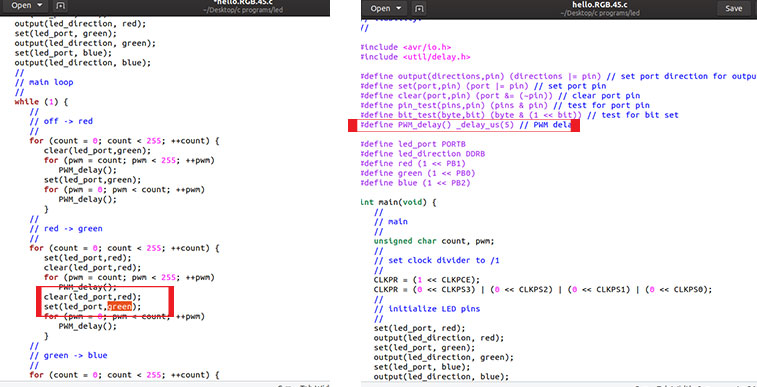
Also I have decreased the delay time and received a very nice effect. - Conclusion
This week I did experimenting with an Arduino and breadboard, doing different things. Even though I was following some tutorials this week, this was a very good learning experience, because I have done research and read lots of articles about electronics and programming. I did my first steps with the Arduino board and IDE gaining the basic knowledge about them and became more confident. I was following tutorials for the first projects, then explored details and started to work on my own ones. While working with electronics, you have to understand the function of every component and the processes between them to succeed. Hope this experience will help in the future, when I will design and programm my own PCBs.
Category:
AlumniDate:
February 3, 2022