Assignment for this week:
Group assignment: Measure the power consumption of an output device
Individual assignment:Add an output device to a microcontroller board you’ve designed, and program it to do something
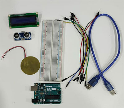
- IntroductionThis week was about output devices. I worked with a servo motor, LCD 1602 monitor, piezo transducer as output devices and used an ultrasonic sensor for measuring the distance as input. This week was easier to work with Arduino and other components as well as programming, because I feel more confident now and it’s easier to navigate in a huge variety of information and tutorials.
Here are the tutorials which have read and found informative: - Servo motor with ArduinoA servo motor is a low-speed, high-torque motor that comes in a variety of sizes. Servo Motor does not normally spin a full 360 degree rotation. Instead it is limited to a range of 180, 270 or 90 degrees. A servo motor is a motor with a built-in “servomechanism”. The servomechanism uses a sensor to monitor the motor shaft position and a controller to control the motor. It is fed a signal that indicates the position that the shaft should be set to. It then moves the motor into the required position.
I used a servo motor, which is limited to 180 degrees rotation angle. The working principle of these motors is following: a PWM signal with a period of 20 ms is used to control the motors. A signal of 20 ms has a frequency of 50 Hz. If the pulse width is 1ms, that will cause the servo shaft to rest at the 0 degree position. The pulse width of 1.5ms will cause the servo shaft to rest in the 90 degree position, the center of its travel.And finally, the pulse width of 2ms will cause the servo shaft to rest in the 180 degree position. So by varying the width of the pulse between 1 and 2 ms we can control the motor shaft position. (image credit: https://dronebotworkshop.com/servo-motors-with-arduino/ ).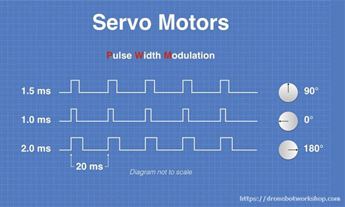
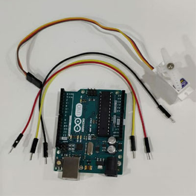
I made a simple connection for the servo motor and run a program from Arduino examples. For this setup I used only an Arduino, a servo motor and jumper wires.
Here is the schematic and connection steps (I have a motor from HiTech brand, wire colors may be different for other brands):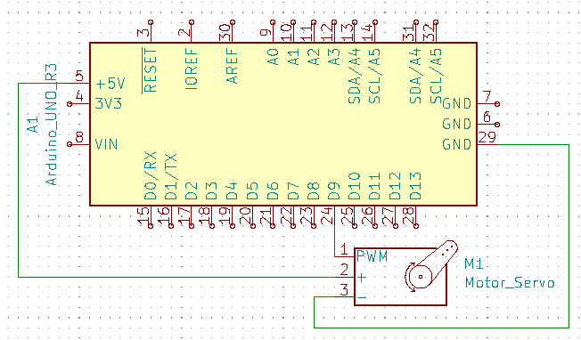
- Connect Ground (Brown) lead of motor to the Ground pin on Arduino using a wire.
- Connect Power (Red) lead of motor to the 5V pin on Arduino using a wire.
- Connect Control (Yellow) lead of motor to the Analog 9 pin on Arduino using a wire.
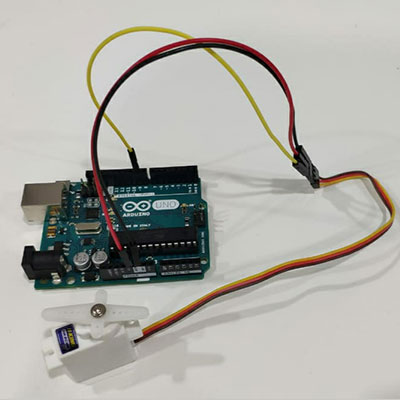
- Connect Arduino to the computer with Arduino IDE
- Go to File → Examples → Examples for any board → Servo Sweep and upload it to the board
/* Sweep
 by BARRAGAN
 This example code is in the public domain.
 modified 8 Nov 2013
 by Scott Fitzgerald
 http://www.arduino.cc/en/Tutorial/Sweep
*/
#include
Servo myservo; // create servo object to control a servo
// twelve servo objects can be created on most boards
int pos = 0; // variable to store the servo position
void setup() {
 myservo.attach(9); // attaches the servo on pin 9 to the servo object
}
void loop() {
 for (pos = 0; pos <= 180; pos += 1) { // goes from 0 degrees to 180 degrees
 // in steps of 1 degree
 myservo.write(pos); // tell servo to go to position in variable 'pos'
 delay(15); // waits 15ms for the servo to reach the position
 }
 for (pos = 180; pos >= 0; pos -= 1) { // goes from 180 degrees to 0 degrees
 myservo.write(pos); // tell servo to go to position in variable 'pos'
 delay(15); // waits 15ms for the servo to reach the position
 }
}
This is a very simple program which makes the motor rotate from 0 to 180 degrees by 1 degree step and then come back to 0 with the same step.
Here you can find the file with the code and the schematic file.
- Distance sensor with LCD and piezo transducerMy other project is something similar to the parktronic system. I used an ultrasonic distance sensor along with LCD1602 display module for Arduino and a piezo transducer for making a sound.
I set up a program in a way, that on LCD we can see the distance of an object from the ultrasonic sensor and if the object is closer than 30cm, the piezo transducer will make a sound for 2 seconds. So let’s see how each of the components here work.Ultrasonic distance sensors use pulses of ultrasonic sound (sound above the range of human hearing) to detect the distance between them and nearby solid objects.It determines the distance to an object by measuring the time taken by the sound to reflect back from that object. The sensors consist of two main components:
– An Ultrasonic Transmitter – This transmits the ultrasonic sound pulses, it operates at 40 KHz
– An Ultrasonic Receiver – The receiver listens for the transmitted pulses. If it receives them it produces an output pulse whose width can be used to determine the distance the pulse travelled.
We have to consider that the speed of sound in air varies with temperature, air pressure and humidity. Since the speed of sound factors into our distance calculation this can affect to get presized readings if there are temperature and humidity changes. At the same time ultrasonics are Independent of light, smoke, dust, color.
To make life easier when working with ultrasonic distance sensors and Arduino, you can install the UltraDistSensor library. For that go to Sketch → Include library → Manage libraries, search and find UltraDistSensor and install it.The LCD1602 display module is a very popular and inexpensive LCD display. It consists of two rows of 16 characters each. It interfaces through a parallel data interface and has an LED backlight. My LCD has an I2C interface module mounted on the back. With this I2C module, you only need two connections to control the LCD.
Arduino has the LiquidCystal_I2C library, which makes working with LCD displays very easy and enjoyable. To install that library, download the .zip file from the link above, go to Sketch → Include library → Add ZIP libraries and upload the .zip file.Piezo transducer uses a material that’s piezoelectric, it actually changes shape when you apply electricity to it. By adhering a piezo-electric disc to a thin metal plate, and then applying electricity, we can bend the metal back and forth, which in turn creates noise. The faster you bend the material, the higher the pitch of the noise that’s produced. This rate is called frequency. Again, the higher the frequency, the higher the pitch of the noise we hear.
It has a very simple connection to the Arduino. One of the two wires (-) is connecting to the Ground and the second one (+) to one of the digital pins.
Arduino has the tone() function which generates a square wave of the specified frequency to the specifed pin. You can also give an argument for the duration of the tone, otherwise the wave continues until a call to noTone().Now let’s see how to connect everything together and make it work.
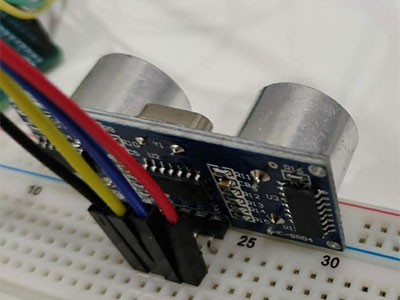
- Attach ultrasonic distance sensor to the arduino breadboard and make following connections:
- Connect VCC of the sensor to the 5V pin on arduino
- Connect Ground of the sensor to the Ground pin on Arduino
- Connect Trigger of the sensor to the digital pin 12 on Arduino
- Connect Echo of the sensor to the digital pin 13 on Arduino
- Connect LCD to the Arduino doing following steps:
- Connect VCC to the 5V same column on the breadboard, where we have 5V connection from Arduino
- Connect Ground to the Ground pin on Arduino
- Connect SDA to the A4
- Connect SCL to the A5
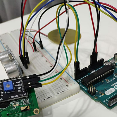
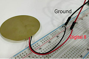
- Attach the piezo transducer to the breadboard so the leads are on the two different rows and make the following connections:
- Connect the positive (red) lead to the digital pin 8 on the Arduino.
- Connect the negative (black) lead to the Ground of Arduino.
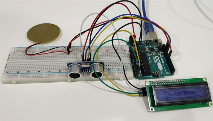
The connections are done. Now connect Arduino to the computer and upload the following code.#include UltraDistSensor.h #include Wire.h #include LiquidCrystal_I2C.h LiquidCrystal_I2C lcd(0x27, 16, 2); UltraDistSensor mysensor; float reading; int piezoPin = 8; void setup() { lcd.init(); // initialize the lcd lcd.backlight(); Serial.begin(9600); mysensor.attach(12,13);//Trigger pin , Echo pin } void loop() { reading = mysensor.distanceInCm(); if (reading >= 400 || reading <= 2) { lcd.clear(); lcd.setCursor(0,0); lcd.print("Out of range"); Serial.print("Out of range"); } else { lcd.setCursor(0,0); lcd.print("Distance is "); lcd.setCursor(0,1); lcd.print(" "); lcd.setCursor(0,1); lcd.print(reading); lcd.print("cm"); Serial.print(reading); } delay(100); if (reading <=30) { tone(piezoPin, 1000, 2000); }; }Here is the result:
Here you can find the file with the code and the schematic file for the distance sensor.
- Attach ultrasonic distance sensor to the arduino breadboard and make following connections:
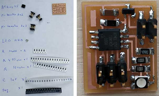
- Hello RGB LEDWhen we were out of quarantine, I started to do missed assignments from electronics. As we didn’t have much time, we were allowed to cut one of Neil’s boards rather than design our own ones. I have decided to make the hello RGB LED board.
First of all I downloaded images for traces and interior of the board and generated G codes in fabmodules.org.

Then I did milling the board and started assembling it.
To do the programming I need to connect the board to fab ISP using a USB cable.
Then download C code and make file from the keynotes. After downloading them and locating in one folder, I started programming by running the following codes:
make -f hello.RGB.45.make
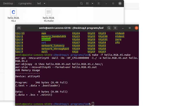
make -f hello.RGB.45.make program-usbtiny
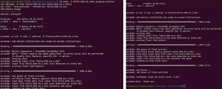
When I connected the board to 9V battery it started to change colors but the green one was never on. So I checked the connections with the multimeter and found out that there is problem with soldering of the LED and the leg fr green is not connected. So I fixed that.
After making sure that board is working I started to play with different arguments: changing color patterns and delay time. It gives the possibility to receive different colors by turning on and off some red, green blue colors. Having the RGB color chart. helps to find the proper combination for desired color.
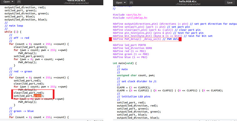
Also I have decreased the delay time and received a very nice effect. - Designing hello.RGB.45 in KiCad
I don’t have chance for fabricating the board as lab is closed due to the pandemic, I was asked to design a board with an output device. I have decided to design one similar to hello.RGB.45. For that:- I have opened KiCAD and opened a New project
- In schematic sheet I chose the components that I need:
- ATtiny45 microcontroller
- Connector headers, 2*2 and 2*3
- Capacitor, 1uF
- Resistanor, 10kohm
- Resistor, 2*1kohm
- Resistor, 1*499ohm
- 9V to 5V Voltage Regulator
- RBG LED
- After chossing the components I have annotated the schematic and assigned the footprints for them
- Then I have done the connections using the wiring tool. To not make my schematic look like a spider web, I have used global label tool and labeled some of the pins with the same name. In that case program assumes that pins are connected.
- When connections are done, I generated netlist
- Import that netlist to the PCB bart of the KiCad
- Some pads wer not correctly labeled on the schematic part. To change this double click on the pad and change the footprint type as well ase the label
- Using the wiriing tool do the connections
- Using the edge cut tool draw the edges
- Export the pcb as svg
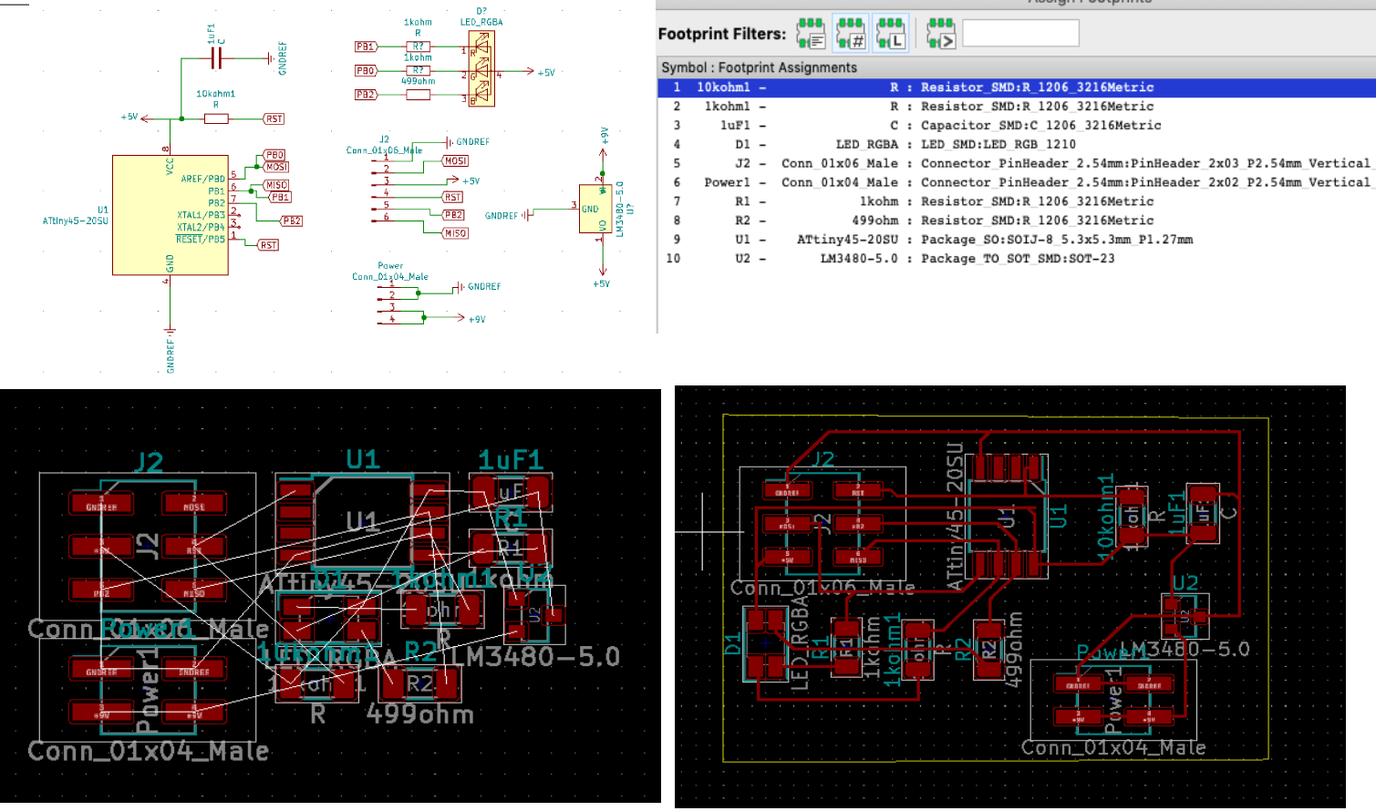
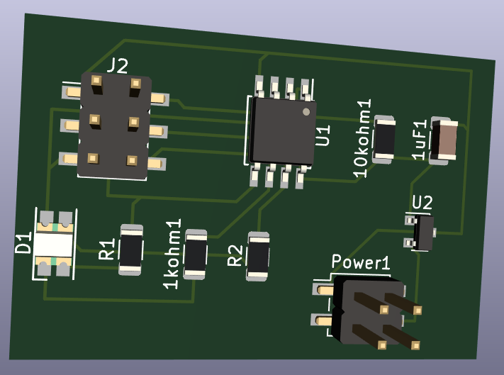
- Go to View ⇛ 3D view to see how will the PCB look like
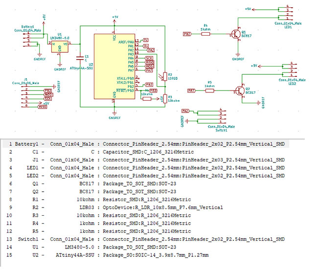
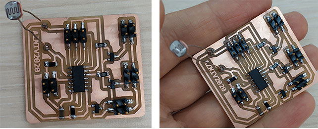
- Output devices in final projectFor my final project I have used LEDs as output devices along with a limit switch and an LDR as input devices. Both of them were used as an indicator for LEDs to be on or off
Further down you can see the components used for my board, the schematic and the board itself.I did the design of the board in KiCAD.
Here is the list of components:- ATtiny44 microcontroller
- 5V voltage regulator
- 2* 10kOhm resistors ( 1 for microcontroller and 1 for LDR)
- 1uF capacitor
- LDR
- 2* BC817 transistors
- 2* 1kOhm resistors to attach to the transistors
- A connector header to connect the switch from the brakes
- A connector header to connect the battery
- Two connector headers for LEDs
- 2*3 connector header to connect the programmer
I added all of the components from the KiCad library and started to connect them.
Then I designed the PCB, exported it as svg and cut the board as it’s described in Electronics production and electronics design weeks. I checked all of the connections by the digital multimeter, seems everything is fine.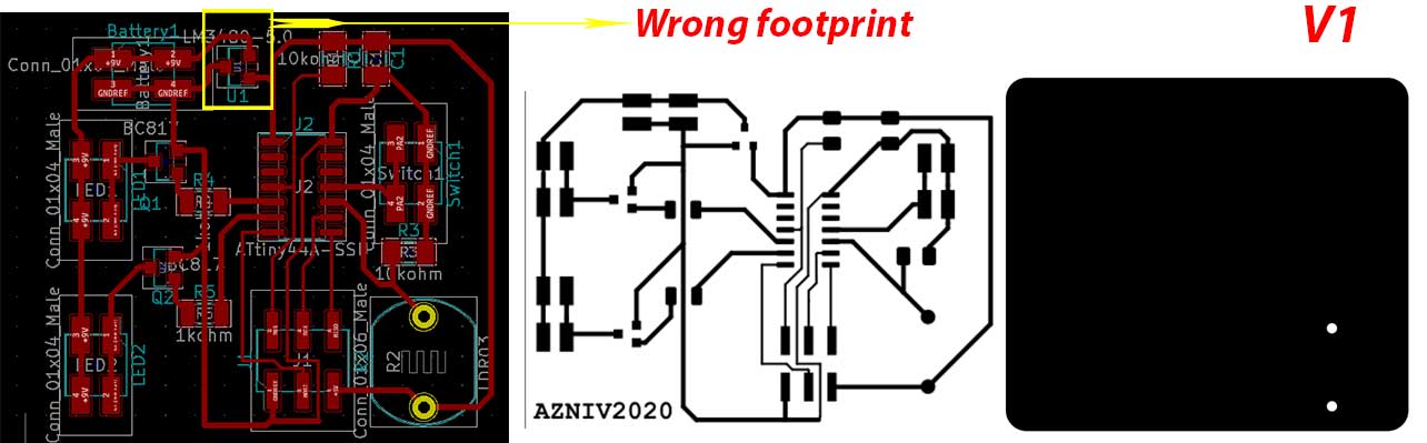
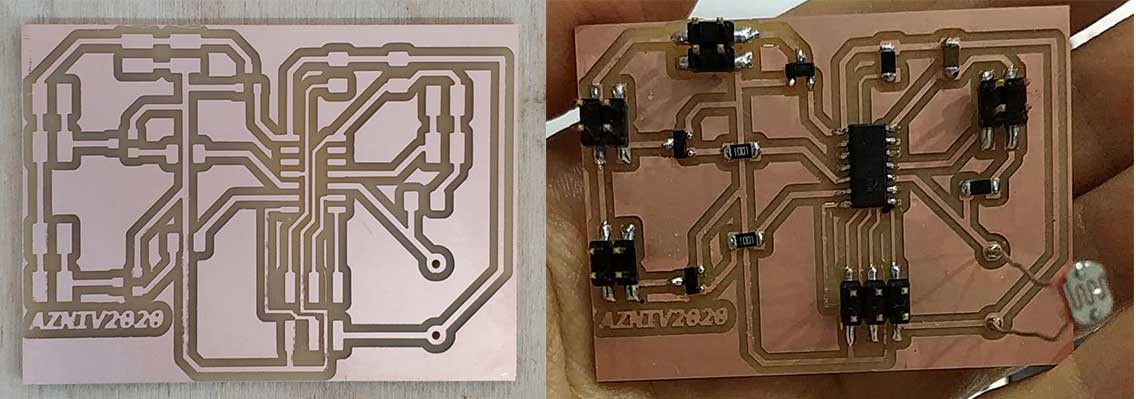
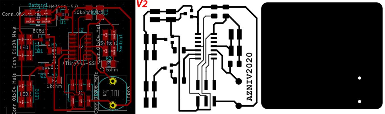
Programming was successful but the board didn’t work. Then I started to check the connections again, all was fine. Afterwards I have checked the footprints and found out that I have a wrong footprint and connections for the voltage regulator. So I have changed the footprint and connections to the proper ones. This time I moved the components closer to each other and my board got smaller.
After assembling the board, I did the programming and this time it worked, hooray.
- Conclusion
This week for me was more enjoyable, because I have more resources and components to play with. I have other ideas as well, for example changing the direction of light source depending on the light distribution in the room, but as we have limited resources because of the lockdown, I will do other projects later on.
When we were back to the lab, I cut and assembled the hello.RGB board and programmed it. Now I feel more confident with the electronics, know how to do troubleshoting, how to test the connections etc. - Fileshello.rgb.led.45 traces and interior
hello.rgb.led.45 programming fileshello.RBG.45 original design files
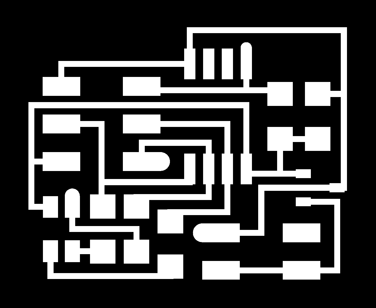
File with the code and the schematic file for the distance sensor.file with the code and the schematic file for servo motor.
Category:
AlumniDate:
February 3, 2022